Chapter 3 ’Web User Graphical Interface’ — Operating Instructions (Tutorial)
Electra VS
-
Version 05.10 149
User Manual - Rev. A
Configuring an SDI System
If the Electra VS is equipped with SDI inputs, this section explains how to
configure and use them.
Recommended SDI Redundancy Topologies
The SDI topology is valid only if it is a set of following sub configurations.
Three SDI redundancy topologies are recommended and are described
below:
SDI redundancy topology (N + M, redundant nodes linked to the same
matrix with dynamic crosspoints).
SDI redundancy topology (N + M, all nodes linked to the same matrix).
SDI redundancy topology (1 + 1, without matrix).
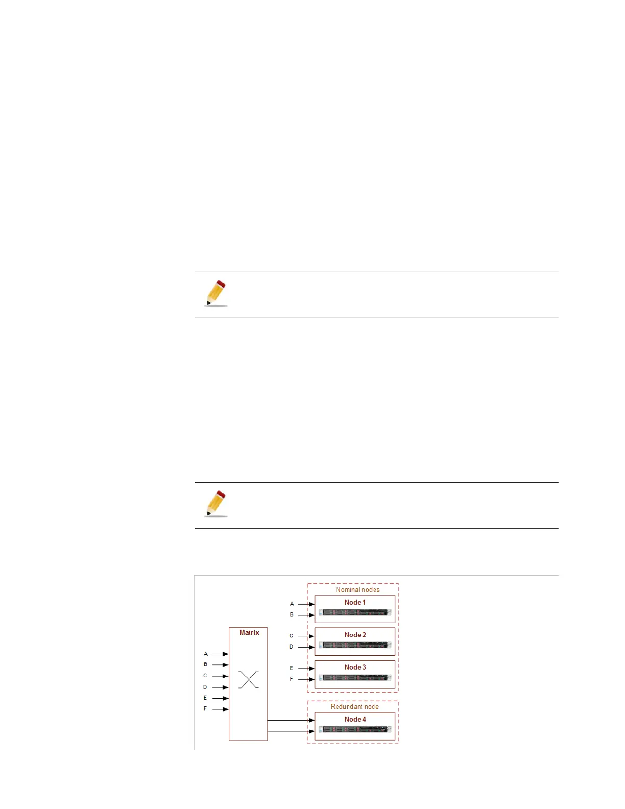
SDI Redundancy Topology (N + M, redundant nodes linked to the same matrix with
dynamic crosspoints)
This topology is recommended and consists of nominal nodes,
redundant nodes and one matrix:
The nominal nodes are directly linked to the SDI sources.
The redundant nodes are linked to the SDI sources via a matrix. The
crosspoints of the matrix are dynamic.
The SDI sources are connected to the nominal nodes and to the
matrix.
Figure 3-99. SDI topology: SDI redundancy - N + M, redundant nodes linked to a matrix
When an SDI topology is created in the Hardware/SDI panel is
recognized as an SDI redundancy topology, all the jobs using the
attached SDI sources will be defined as SDI redundant jobs.
This topology is used to manage redundant SDI sources. The main
source is connected to the main node, the backup source is
connected to the matrix.