5-9
Configuring Serial Interfaces for E1- and T1-Carrier Lines
Serial Interface: Configuring the Physical Layer
If you are not sure which type of cable you have, this chapter provides
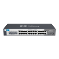
illustrations of the three cable connectors. For example, Figure 5-4 shows the
pinouts for ProCurve Networking’s implementation of the V.35 cable connec-
tor and lists how each pin is used.
Figure 5-4. ProCurve Networking’s V.35 Cable Connector
M/34 (“34-pin M-block“) connector pinout
Pin Signal/Circuit Name
A Unused
B Signal Ground
C RTS_A, Request to Send A
D CTS_A, Clear to Send A
E DSR_A, Data Set Ready A
F DCD_A, Data Carrier Detect A
H DTR_A, Data Terminal Ready A
J Unused
K TM_A, Test Mode A
L Unused
N Unused
N Unused
P TD_A, Send Data A
R RD_A, Receive Data A
S TD_B, Send Data B
T RD_B, Receive Data B
U ETC_A, Terminal Timing A
V RCLK_A, Receive Timing A
W ETC_B, Terminal Timing B
X RCLK_B, Receive Timing B
Y TCLK_A, Send Timing A
AA TCLK_B, Send Timing B
M, Z, BB through FF, and MM are reserved for future
international standardization, HH through LL are reserved for
country-specific standards
V.35
 Loading...