5-10
Configuring Serial Interfaces for E1- and T1-Carrier Lines
Serial Interface: Configuring the Physical Layer
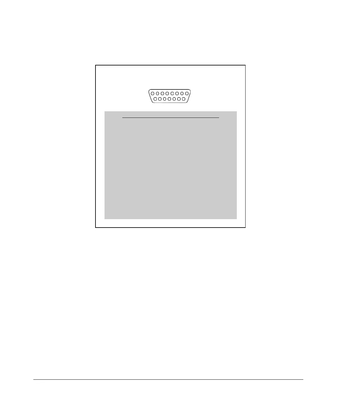
Figure 5-5 shows the pinouts for ProCurve Networking’s implementation of
the X.21 cable connector and lists how each pin is used.
Figure 5-5. ProCurve Networking’s X.21 Cable Connector
18
915
X.21
DB-15 (DA-15) X.27-compatible connector pinout
Pin Signal/Circuit Name
1 Unused
2 TD_A, Transmit A
3 RTS_A, Request to Send A
4 RD_A, Receive Data A
5 CTS_A, Clear to Send A
6 RCLK_A, Receive Timing A
7 Unused
8 Signal Ground
9 TD_B, Transmit Data B
10 RTS_B, Request to Send B
11 RD_B, Receive Data B
12 CTS_B, Clear to Send B
13 RCLK_B, Receive Timing B
14 Unused
15 Reserved for future international use
 Loading...