5-11
Configuring Serial Interfaces for E1- and T1-Carrier Lines
Serial Interface: Configuring the Physical Layer
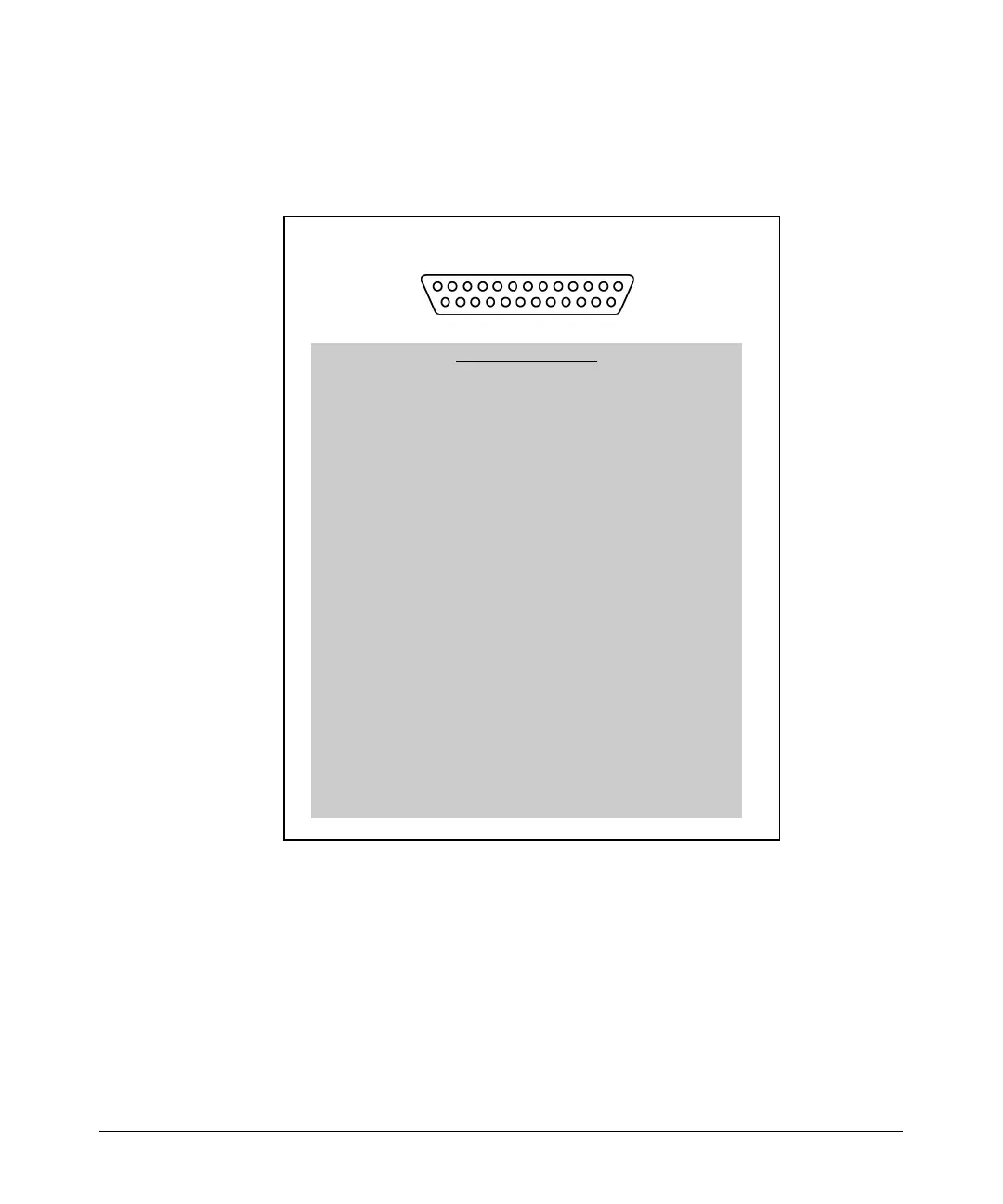
If you have an EIA 530 cable that you purchased from another vendor, the
ProCurve Secure Router supports it. You can also use Figure 5-6, which shows
the pinouts for EIA 530, to create this type of connector.
Figure 5-6. Connector for an EIA 530 Cable
Whichever cable you use, the serial module supports up to 10 Mbps.
113
14 25
DB-25
DB-25 connector pinout
Pin Signal/Circuit Name
1 Shield
2 TD_A, Transmitted Data A
3 RD_A, Received Data A
4 RTS_A, Request to Send A
5 CTS_A, Clear to Send A
6 DCR_A, DCE Ready A
7 Signal Ground
8 RLSD_A, Received Line Signal Detector A
9 RSECTC_B, Receiver Signal Element Timing (DCE Source) B
10 RLSD_B, Received Line Signal Detector B
11 TSETT_B, Transmitter Signal Element Timing (DTE Source) B
12 TSETC_B, Transmitter Signal Element Timing (DCE Source) B
13 CTS_B, Clear to Send B
14 TD_B, Transmitted Data B
15 TSETC_A, Transmitter Signal Element Timing (DCE Source) A
16 RD_B, Received Data B
17 RSETC, Receiver Signal Element Timing (DCE Source) A
18 LL, Local Loopback
19 RTS_B, Request to Send B
20 DTR_A, DTE Ready A
21 RL, Remote Loopback
22 DCR_B, DCE Ready B
23 DTR_B, DTE Ready B
24 TSETT_A, Transmitter Signal Element Timing (DTE Source) A
25 TM, Test Mode
 Loading...