Input and Output Check
SM Appendix 3-399 D086/D087
Appendix:
SP Mode
Tables
3.9 INPUT AND OUTPUT CHECK
3.9.1 INPUT CHECK TABLE
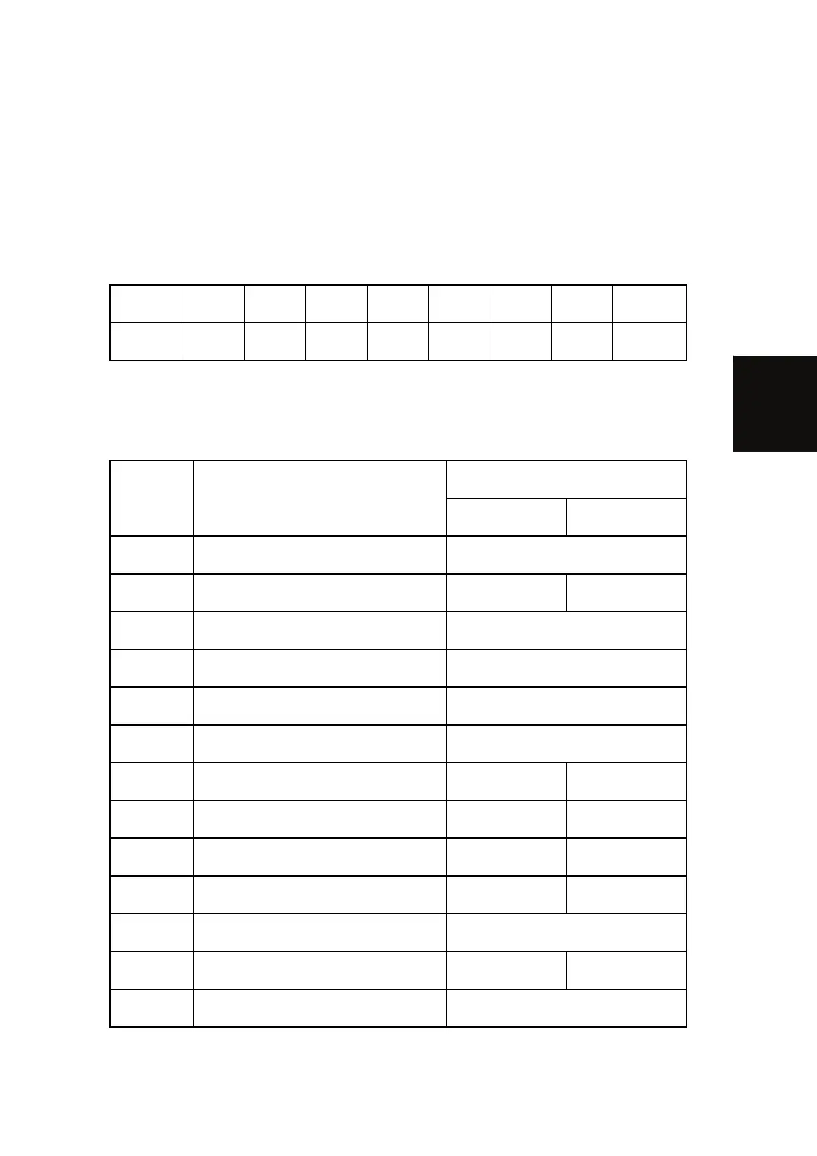
When entering the Input Check mode, 8 digits display the result for a section. Each digit
corresponds to a different device as shown in the table.
Bit No. 7 6 5 4 3 2 1 0
Result
0 or 1 0 or 1 0 or 1 0 or 1 0 or 1 0 or 1 0 or 1 0 or 1
Copier
5803 Description
Reading
0 1
5803 1 2nd Tray Size Detection See table 2 following this table.
5803 2 1st Tray Set Detection Set Not set
5803 3 1st Tray Paper Height Sensor1 See table 1 following this table.
5803 4 1st Tray Paper Height Sensor2 See table 1 following this table.
5803 5 2nd Tray Paper Height Sensor1 See table 1 following this table.
5803 6 2nd Tray Paper Height Sensor2 See table 1 following this table.
5803 7 1st Tray Paper End Detection No paper Paper remaining
5803 8 2nd Tray Paper End Detection No paper Paper remaining
5803 9 1st Tray Upper Limit Sensor Not upper limit Upper limit
5803 10 2nd Tray Upper Limit Sensor Not upper limit Upper limit
5803 11 Bypass Paper Width Detection See table 3 following this table.
5803 12 Bypass Paper End Detection No paper Paper remaining
5803 13 Bypass Paper Length Detection See table 3 following this table.
 Loading...