HIGH DATA RATE RECEIVER
HDR-4G+ USER’S MANUAL
Ref. DTU 100782
Is.Rev 3.5
Date: June 1, 2021
© Safran Data Systems – IMP000074 e14r1
This document is the property of Safran Data Systems.
It cannot be duplicated or distributed without expressed written consent.
DVB-S Transport Layer: Reed Solomon Code 3.3.7.3
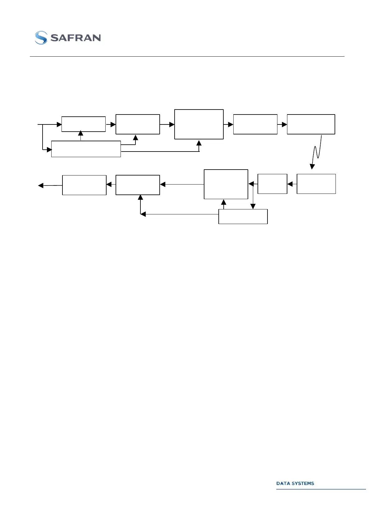
As defined in § 4.7 of ECSS-E50-01 draft 0.5, the concatenation principle correspond to the following
processes but with some interaction between them as depicted in next figure:
Row/column
interleaving with
sync. Bytes
insertion
Bytes to Symb.
transformation
MTCM encoding
8PSK modulation
Sync bytes
search/global sync.
Symb. to bytes
transformation
/deinterleaving
Synchronization for
frame/RS and scrambler
hronisation
Figure 30: Concatenation Principle
Synchronized Randomization 3.3.7.3.1
Within the transmitter, the input digital data is randomized with a PRBS whose characteristics are:
Generating polynomial: 1+x14+x15
Initialization sequence: 100101010000000
This sequence is loaded at the beginning of each transport frame. Due to the chosen polynomial, it is
possible to output the data by bytes with the help of a shifted calculation , i.e. out bit1 or MSB of byte =
reg15 EX-OR reg14, out bit2 = reg14 EX-OR reg13, out bit3 = reg13 EX-OR reg12, out bit4 = reg12
EX-OR reg11, out bit5 = reg11 EX-OR reg10, out bit6 = reg10 EX-OR reg9, out bit7 = reg9 EX-OR
reg8 and out bit8 or LSB of byte = reg8 EX-OR reg7 and then shift by 8 bits the contents of the register
before calculating the PRBS sequence for the next byte.
It should be noticed that in order to avoid tedious rate changes, the data have to be captured at the
interface by group of 238 bytes with one blank byte in front and 16 blank bytes at the rear. During the
blank bytes, the randomization is shifting but the enable bit must be downed to zero.
The randomization processing is described on next figure.