HIGH DATA RATE RECEIVER
HDR-4G+ USER’S MANUAL
Ref. DTU 100782
Is.Rev 3.5
Date: June 1, 2021
© Safran Data Systems – IMP000074 e14r1
This document is the property of Safran Data Systems.
It cannot be duplicated or distributed without expressed written consent.
Demodulator inputs description 2.2.2.2.3
Inputs into the frame synchronizer are available on SMA connectors in ECL electrical format or on
RJ45 connector in LVDS electrical format.
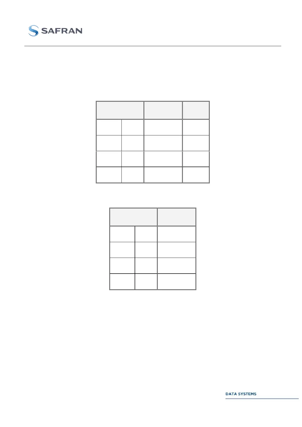
The following tables show the different configurations for both single and dual channel input.
Table 7: Single channel demodulator input modes
Table 8: Dual channel demodulator input mode