HIGH DATA RATE RECEIVER
HDR-4G+ USER’S MANUAL
Ref. DTU 100782
Is.Rev 3.5
Date: June 1, 2021
© Safran Data Systems – IMP000074 e14r1
This document is the property of Safran Data Systems.
It cannot be duplicated or distributed without expressed written consent.
Constellation Mapper for 4D-8PSK-TCM 3.3.7.2.3
The constellation mapper principles are given in next figures for the four possible efficiencies of this
modulation (i.e., 2 bits/channel-symbol, 2.25 bits/channel-symbol, 2.5 bits/channel-symbol and 2.75
bits/channel-symbol). These mappers implement the straightforward logical mapping described in the
equations below. The correspondence between the signals Z
(i)
at the input of the modular and the
8PSK phase states of the constellations follows a natural mapping (i.e., 0, 1, 2 …, 7).
If Z
(i)
represents the signals (three lines) at the input of the modulator with Z
(0)
being the signal set of
the first constellation and Z
(3)
being the signal set of the fourth constellation, the signal set Z
(i)
is
represented by the following equation. This representation shows that the bits which are common to
each vector set (shown in the first part of right-hand side of each equation) are sensitive to a phase
rotation of /4 and will be differentially encoded.
(i) Equation for 2 bits/channel symbol efficiency:
8mod
0
2
0
4
1
1
1
1
24
023
2
3
467
6
7
158
)3(
)2(
)1(
)0(
xxx
x
x
xxx
x
x
xxx
Z
Z
Z
Z
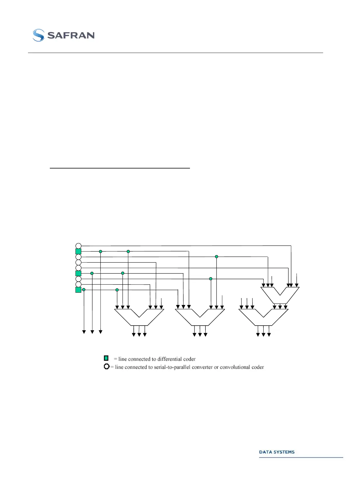
Figure 22: Constellation Mapper for 2 bits/channel-symbol
x0
x1
x2
x3
x4
x5
x6
x7
x8
0
+
+
+
+
2 1 0
2 1 0 2 1 0
2 1 0
2 1 0
2 1 0 2 1 0
2 1 0
2 1 0
2 1 0 2 1 0 2 1 0
0
0
0
Z
(1)
Z
(1)
Z
(1)
2 1
0
Z
(2)
Z
(2)
Z
(2)
2 1
0
Z
(0)
Z
(0)
Z
(0)
2 1
0
Z
(3)
Z
(3)
Z
(3)
2 1
0
Z
(1)
Z
(1)
Z
(1)
2 1
0