HIGH DATA RATE RECEIVER
HDR-4G+ USER’S MANUAL
Ref. DTU 100782
Is.Rev 3.5
Date: June 1, 2021
© Safran Data Systems – IMP000074 e14r1
This document is the property of Safran Data Systems.
It cannot be duplicated or distributed without expressed written consent.
Demodulator board 2.1.3
Overview 2.1.3.1
The demodulator assembly consists in:
- the mother board: PCI-e board with FPGA
- the IF input board
- the I/O interface board
- the set of cables and I/O connectors
The I/O mezzanine in its standard version provides both ECL I/O and LVDS I/O.
Separate IF inputs 2.1.3.2
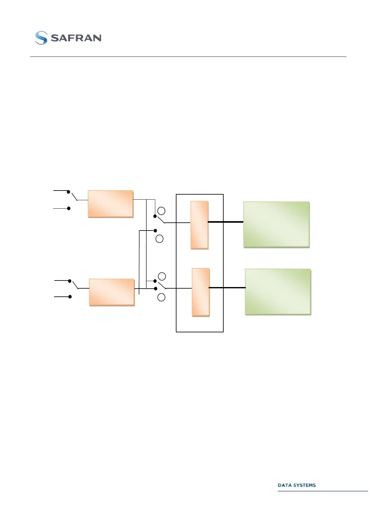
The following figure gives the diagram of the IF input stage of the demodulator board.
Figure 8: Demodulator input stage with separate IF inputs
The demodulator board provides double 720 MHz/1.2GHz/2,4GHz IF inputs. These configurations are
exclusive. The selection between configurations is done by basic menu selection.
Analogue
720 MHz
1.2 GHz input
2,4GHz Input
Analogue
720 MHz
1.2 GHz input
2,4GHz Input