HIGH DATA RATE RECEIVER
HDR-4G+ USER’S MANUAL
Ref. DTU 100782
Is.Rev 3.5
Date: June 1, 2021
© Safran Data Systems – IMP000074 e14r1
This document is the property of Safran Data Systems.
It cannot be duplicated or distributed without expressed written consent.
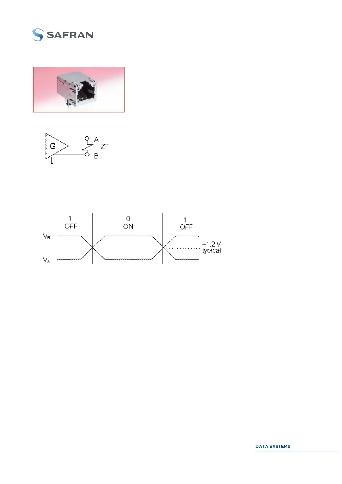
LVDS Connector: EMBASE RJ45 CAT. 6
LVDS differential outputs must be terminated as follows:
ZT = Termination impedance = 100
The output level is adjusted around the typical 1.2 V offset, with a peak-to-peak amplitude varying from
250 mV to 450 mV.
Channel A & Channel B I/Os description 2.2.2.2.1
The Outputs of the demodulators depend on:
the selected option
the demodulation mode
the selected soft decision output
the selected Data format output (CADU)
and the setting of the Output Mode parameter
The following table shows the different configurations for both Demodulator A and Demodulator B
(standard outputs).