HIGH DATA RATE RECEIVER
HDR-4G+ USER’S MANUAL
Ref. DTU 100782
Is.Rev 3.5
Date: June 1, 2021
© Safran Data Systems – IMP000074 e14r1
This document is the property of Safran Data Systems.
It cannot be duplicated or distributed without expressed written consent.
Configuring the modulator and the format input 3.6.4.1.2
Direct input to the modulator can be obtained by following these guidelines:
Use FPGA #1 for modulator
Activate (mount) MDU1, MFI, and IFO in the global table
In MDU 1:
o Set MDU1 to the desired settings in terms of modulation, carrier frequency, RRC
filtering, PCM code and phase rotation.
o Set the Bitrate to the target overall bitrate:
In symbol mode, multiply the desired clock rate by the order of modulation
In data mode, multiply the desired clock rate by the input parallelism
o Declare the Format Input as the input to the modulator
In MFI:
o Set the input type as standard
o Select the data scheme (Hard Symbol or Data with required parallelism)
Connect the required signals to the modulator board (please refer to Table 15: connectors
allocation, single Ended ECL
)
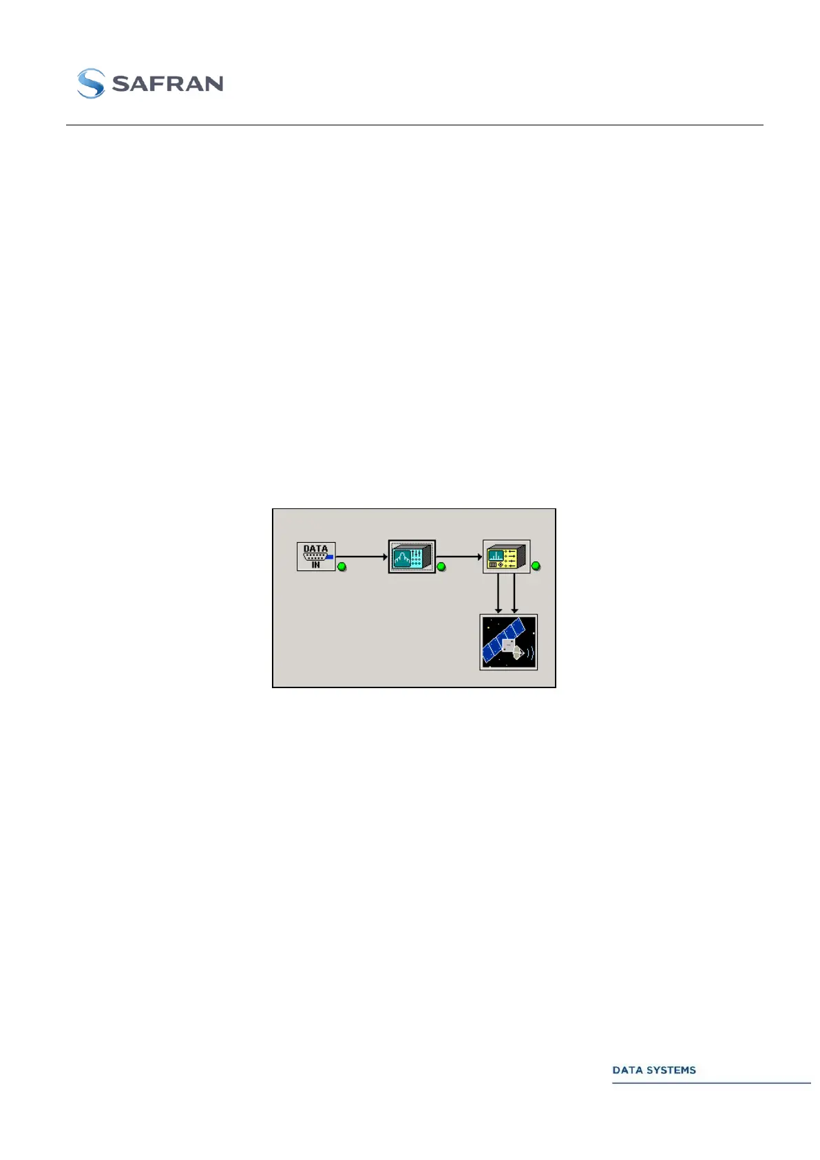
Below lies an example of a correct setting for direct input of serial data to a QPSK, 100 Mbps
modulator.
Figure 72: direct modulator input, as seen in the main modulator window