HIGH DATA RATE RECEIVER
HDR-4G+ USER’S MANUAL
Ref. DTU 100782
Is.Rev 3.5
Date: June 1, 2021
© Safran Data Systems – IMP000074 e14r1
This document is the property of Safran Data Systems.
It cannot be duplicated or distributed without expressed written consent.
Three choices are possible concerning the output routing:
- m = 100 %, n = 0 %: channel A is directly routed to the output. No combining is performed.
- m = 0 %, n = 100 %: channel B is directly routed to the output. No combining is performed.
- m and n are dynamically adjusted by the combining system. This is described in the “Signal
processing” section.
Signal Processing 3.5.3
When both channels are locked, the combining system identifies and compensates the relative phase
ambiguity before combining. The supported modulations are QPSK, OQPSK and 8PSK.
Two combining modes exist:
- Best channel: only the signal of the channel with the best Eb/N0 is fed through the combining
system.
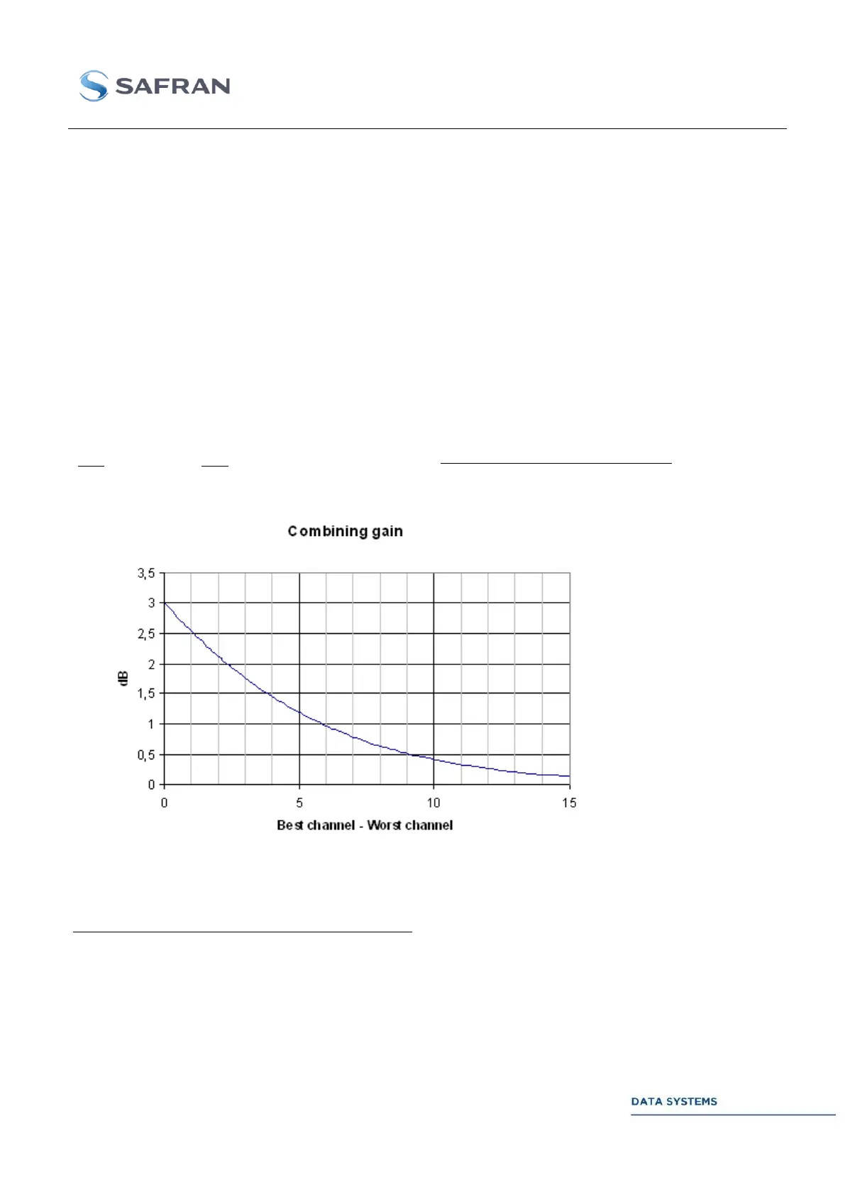
- Combining: signals of both channels are combined using optimal weighting. In this case, the
combining gain versus the best channel is:
10
)()(
10
_
)(
0
)(
0
__
10110
channelbestchannelworst dBmLeveldBmLevel
channelbest
dB
combining
dB
Log
N
Eb
N
Eb
The relative amplitude of a channel (A or B) is given by:
100
____
_
x
BChannelAmplitudeAChannelAmplidude
ChannelAmplitude
The sum of the relative signal amplitudes is 100. The best case (3-dB gain) is achieved when both IF
Receivers are locked onto equal-strength signals.