HIGH DATA RATE RECEIVER
HDR-4G+ USER’S MANUAL
Ref. DTU 100782
Is.Rev 3.5
Date: June 1, 2021
© Safran Data Systems – IMP000074 e14r1
This document is the property of Safran Data Systems.
It cannot be duplicated or distributed without expressed written consent.
Ambiguity resolution by the DPUs 3.4.13.2
The ambiguity resolution is done by a specific process consisting in analysing the timing of the received
CADU at the input of the DPUs and allowing a feed-back towards the DMU to route the data flows to
the right DPUs. For that, The DPUs expect to receive the CADUs with a specific arrangement.
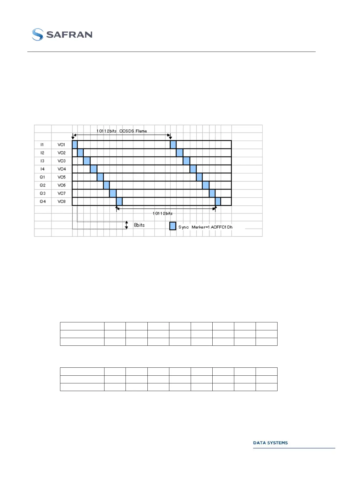
For example with the 16 QAM – 8 DPU mode, the received data flows at the inputs of the DPUs is
given in the following figure. An offset of 1 byte is inserted between the successive CADUs.
Figure 52: 8 DPU Data Flow for automatic ambiguity resolution
An identical mechanism is implemented for the QPSK – 4 DPU mode and the QPSK – 2 DPU mode.
The following tables give the correspondence between the offsets and the DPUs for the different
modes. For each mode, two mapping are today available and selectable from the GUI (parameter: DPU
Map in the DPU CADU window).
16QAM – 8 DPU, DPU Map = 0
16QAM – 8 DPU, DPU Map = 1