HIGH DATA RATE RECEIVER
HDR-4G+ USER’S MANUAL
Ref. DTU 100782
Is.Rev 3.5
Date: June 1, 2021
© Safran Data Systems – IMP000074 e14r1
This document is the property of Safran Data Systems.
It cannot be duplicated or distributed without expressed written consent.
When the board is fitted with differential ECL the only mode available is Serial data mode as only
one data input is available. In this case the serial data mode is forced, regardless of the setting that is
set in the configuration table.
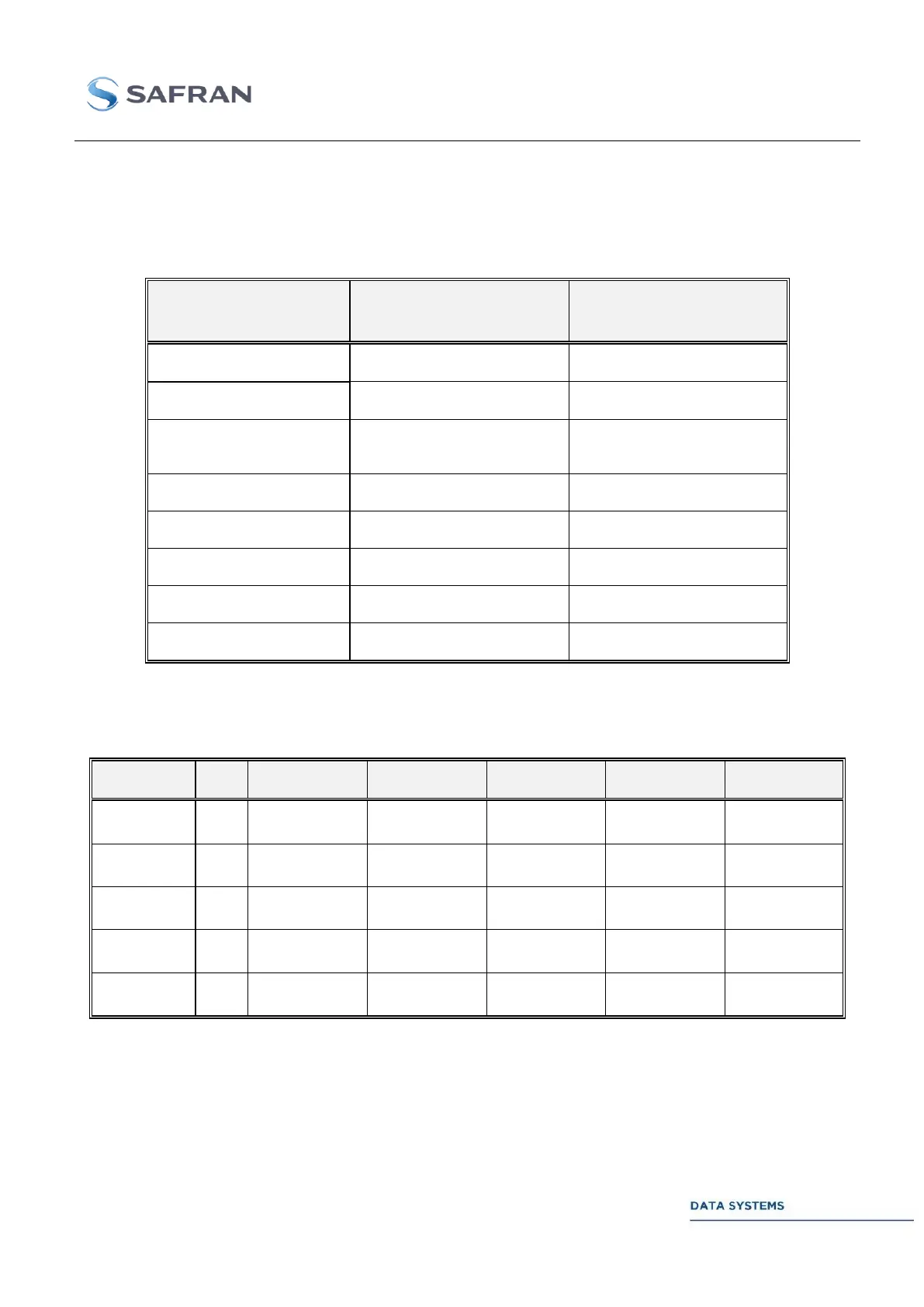
Here are the possible schemes depending on the modulation and the data type:
HARD SYMBOL
(SINGLE ENDED ECL ONLY)
Yes, single clock, offset
introduced internally to the
modulator.
Table 14: modulations and input modes
Here is the table of connector allocation depending on the data scheme, for single ended ECL:
Table 15: connectors allocation, single Ended ECL
(1): I/Q/Z/X data refers to direct symbol mapping. For example, I/Q/Z mode in 8PSK means that each
bit fed to the input will be directly used to map the symbol using the mapping selected in the connected
MDU. In BPSK, only I is relevant. In QPSK/OQPSK, I and Q are relevant. In 8PSK I, Q, and Z are
relevant. In 16APSK and 16QAM, I, Q, Z and X are relevant.
(2): the convention for data merging is D1 D2 D3 D4, D1 being the MSB and first bit transmitted.