HIGH DATA RATE RECEIVER
HDR-4G+ USER’S MANUAL
Ref. DTU 100782
Is.Rev 3.5
Date: June 1, 2021
© Safran Data Systems – IMP000074 e14r1
This document is the property of Safran Data Systems.
It cannot be duplicated or distributed without expressed written consent.
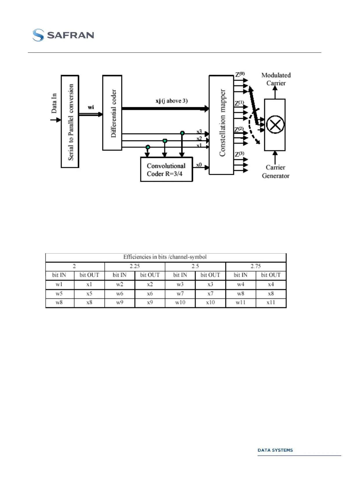
Figure 19: Structure of the 4D 8PSK-TCM Coder/Mapper
Differential Coder 3.3.7.2.1
The differential coder depicted in Figure 20 is used to eliminate phase ambiguity on carrier
synchronization for each modulation efficiency. Table 10 gives the bit reference at input and output of
the differential coder in each case.
Table 10: Bit Mapping for Differential Coder
An example of differential encoder connections is given in Figure 20 for the 2 bits/channel-symbol
case. The structure of the modulo 8 adder is also shown; it is applicable to both the coder mapper and
differential coder.