HIGH DATA RATE RECEIVER
HDR-4G+ USER’S MANUAL
Ref. DTU 100782
Is.Rev 3.5
Date: June 1, 2021
© Safran Data Systems – IMP000074 e14r1
This document is the property of Safran Data Systems.
It cannot be duplicated or distributed without expressed written consent.
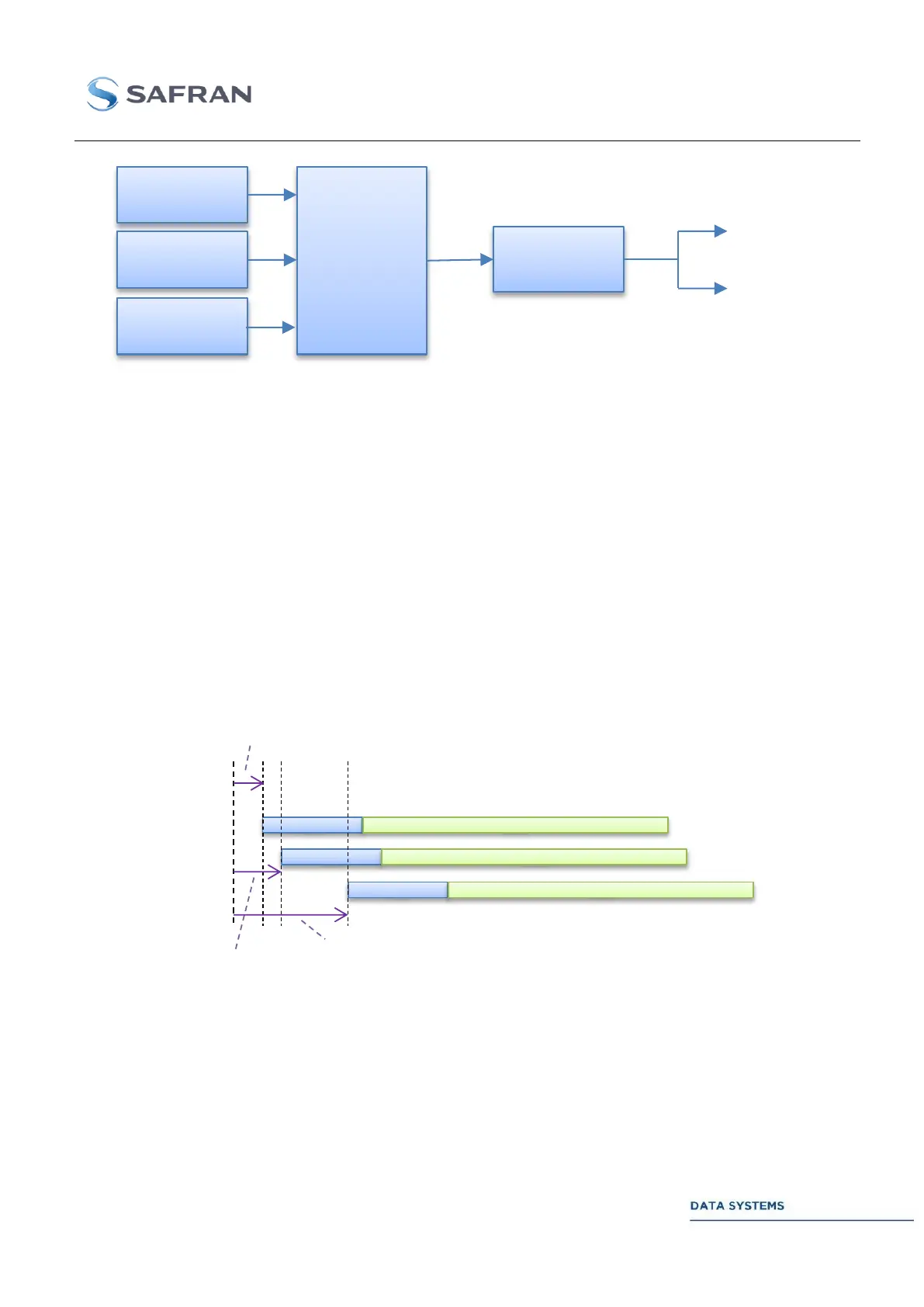
Figure 59: Example of 3 DGUs merging for simulation of independent I/Q/C transmission in 8PSK
The total number of data units that can be connected simultaneously to a modulating unit can be 1, 2, 3
or 8.
Given a modulation order n (ex: 3 in 8PSK):
I/Q/C… synchronization is guaranteed only when the number of DGUs is equal to n
the convention for bit to symbol mapping is: DGU1 I, DGU2 Q, DGU3 C (or Z) and so
on.
Multi-DGU support is enabled by adjusting the number of DGUs in the modulator’s GUI or the TCP/IP
interface.
Each data unit has an adjustable starting offset, in bits. This enables to offset multiple data streams
with a predefined scheme in order to ease multi-channel ambiguity resolution at the receiving end.
Figure 60: Example of 3 DGUs with different offsets
DGU1
Max : 1,6 Gbps
DGU2
Max : 1,6 Gbps
PCM
TCM
8PSK
Modulator
Max : 4,8 Gbps
I
Q
Symbols
To IF1 and/or IF2
DGU3
Max : 1,6 Gbps
C
ASM data
ASM data
ASM data
Offset DGU1
Offset DGU2
Offset DGU3