HIGH DATA RATE RECEIVER
HDR-4G+ USER’S MANUAL
Ref. DTU 100782
Is.Rev 3.5
Date: June 1, 2021
© Safran Data Systems – IMP000074 e14r1
This document is the property of Safran Data Systems.
It cannot be duplicated or distributed without expressed written consent.
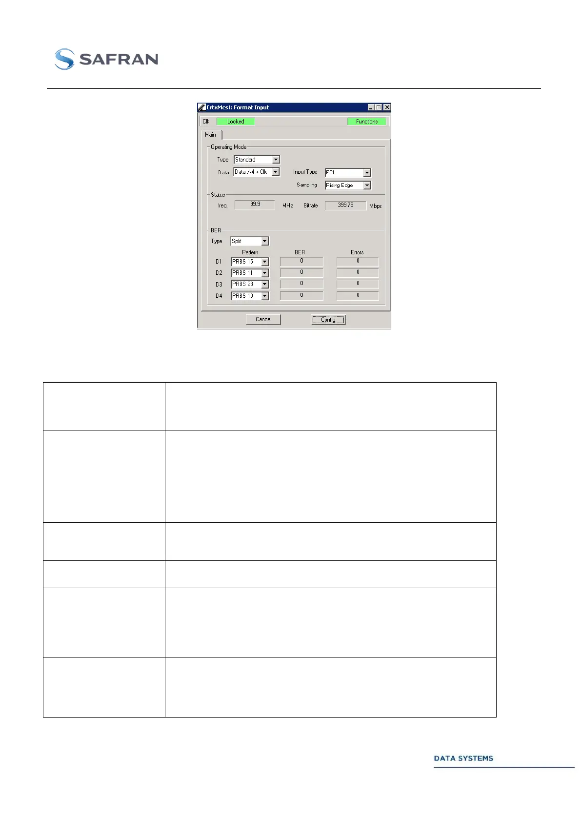
Figure 180: Data //4
Control 4.5.8.4.2.1
Specifies the type of Input scheme:
- Standard (HDR4G baseline)
- Custom (Customer specific, may require dedicated HW and/or
licence)
For standard input mode, specifies the input format to the modulator:
- Serial data + clk: 1 bit data + clk
- Data //2 + clk: 2 bits data + clk with clock rate at half the bitrate
- Data //3 + clk: 3 bits data + clk
- Data //4 +clk: 4 bits data +clk
- Data //8 +clk: 8 bits data + clk (coming soon)
- Hard Symbol +clk: n bits + clk, with n being the order of the modulation
selected in the connected MDU.
Specifies the electrical standard for the input:
- ECL (on the modulator board)
- LVDS (on the I/O panel – coming soon)
Enable selection of either rising or falling edge with respect to clk on the
interface
Specifies the BER scheme on the input:
- Merged: all parallel bits are merged on a single stream before
entering the BER estimator
- Split: parallel bits are treated separately, with independent Pattern
selection. Parallel bits can results from either “Hard symbols” or
“data” in //2, 3, 4.
BER – DATA,
OR
D1, D2, D3, D4
OR
I, Q, Z, X
Enable selection of the BER pattern to test among PRBS 7, 10, 11, 15, 23 or
31 for each possible stream to test (merged, or one for each input bit). “OFF”
disables PRBS testing.