Creating a ShopTurn program
7.13 Changing program settings
Turning
246 Operating Manual, 03/2013, 6FC5398-8CP40-3BA1
Parameters
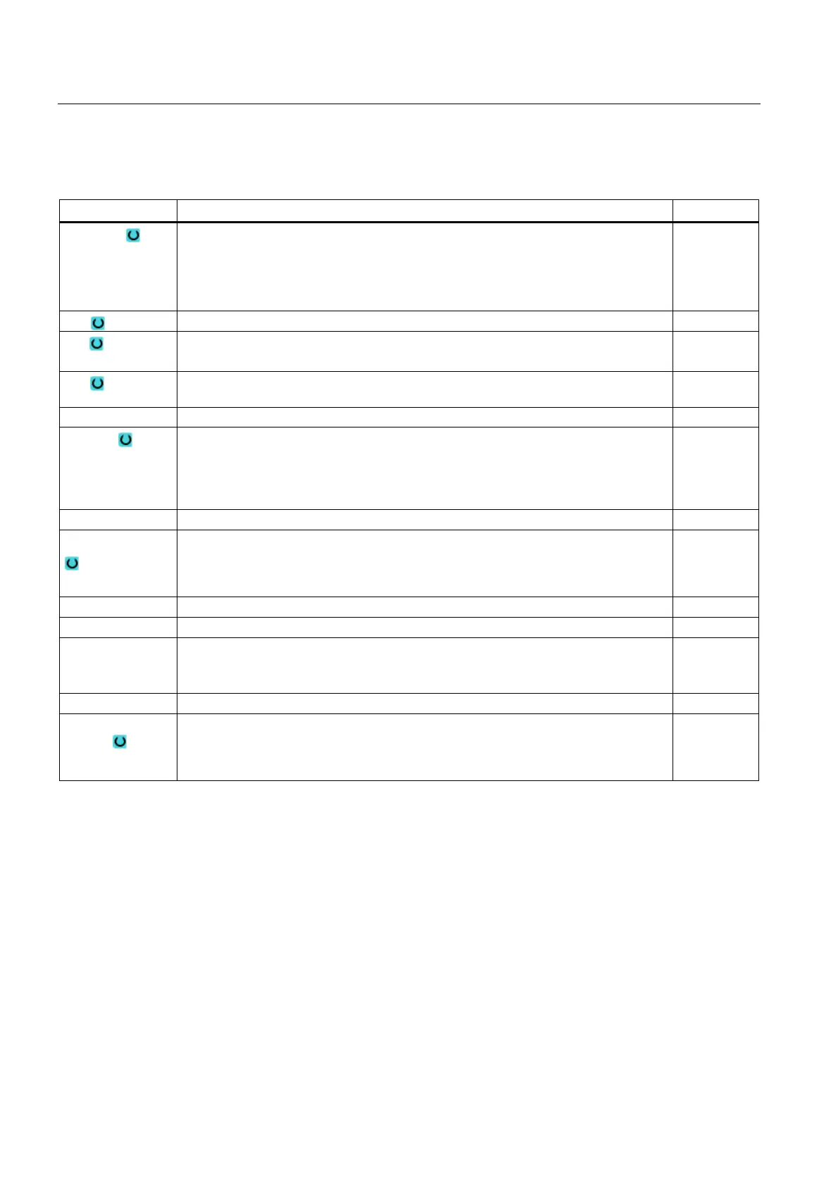
Parameter Description Unit
Retraction Lift mode
• simple
• Extended
• all
XRA Retraction plane X external ∅ (abs) or retraction plane X referred to XA (inc) mm
XRI Retraction plane X internal ∅ (abs) or retraction plane X referred to XI (inc)
- (only for retraction "extended" and "all")
mm
ZRA Retraction plane Z front (abs) or
retraction plane Z referred to ZA (inc)
mm
ZRI Retraction plane Z rear – (only for retraction "all") mm
Tailstock Yes
• Tailstock is displayed for simulation / simultaneous recording
• When approaching/retracting, the retraction logic is taken into account
No
XRR Retraction plane – (only "Yes" for tailstock) mm
Tool change point
Tool change point
• Work (Workpiece Coordinate System)
• Machine (Machine Coordinate System)
XT Tool change point X mm
ZT Tool change point Z mm
SC Safety clearance (inc)
Acts in relation to the reference point. The direction in which the safety clearance is
active is automatically determined by the cycle.
mm
S1 Maximum speed, main spindle rev/min
Machining
direction
Milling direction:
• Climbing
• Conventional