Programming technology functions (cycles)
8.3 Contour turning
Turning
352 Operating Manual, 03/2013, 6FC5398-8CP40-3BA1
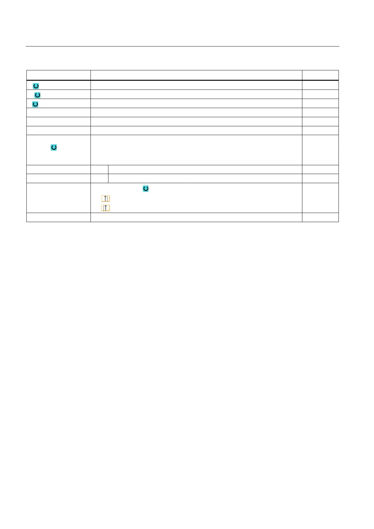
Parameters Description Unit
X End point X ∅ (abs) or end point X (inc) mm
K Circle center point K (abs or inc) mm
I Circle center point I ∅ (abs or circle center point I (inc) mm
α1 Starting angle to Z axis Degrees
β1 End angle to Z axis Degrees
β2 Opening angle Degrees
Transition to next
element
Type of transition
• Radius
• Chamfer
Radius R Transition to following element - radius mm
Chamfer FS Transition to following element - chamfer mm
CA Grinding allowance
• Grinding allowance to right of contour
•
Grinding allowance to left of contour
mm
Additional commands Additional G code commands
Contour element "End"
The data for the transition at the contour end of the previous contour element is displayed in
the "End" parameter screen.
The values cannot be edited.
8.3.5 Entering the master dimension
If you would like to finish your workpiece to an exact fit, you can input the master dimension
directly into the parameter screen form during programming.
Specify the master dimension as follows:
F<Diameter/Length> <Tolerance class> <Tolerance quality>
"F" identifies that a master dimension follows, i.e. in this case, a hole.
Example: F20h7
Possible tolerance classes:
A, B, C, D, E, F, G, H, J, T, U, V, X, Y, Z
Upper-case characters: Holes
Lower case letters: Shafts
Possible tolerance qualities:
1 to 18, if they are not restricted by DIN standard 7150.