Programming technology functions (cycles)
8.2 Rotate
Turning
Operating Manual, 03/2013, 6FC5398-8CP40-3BA1
321
- OR
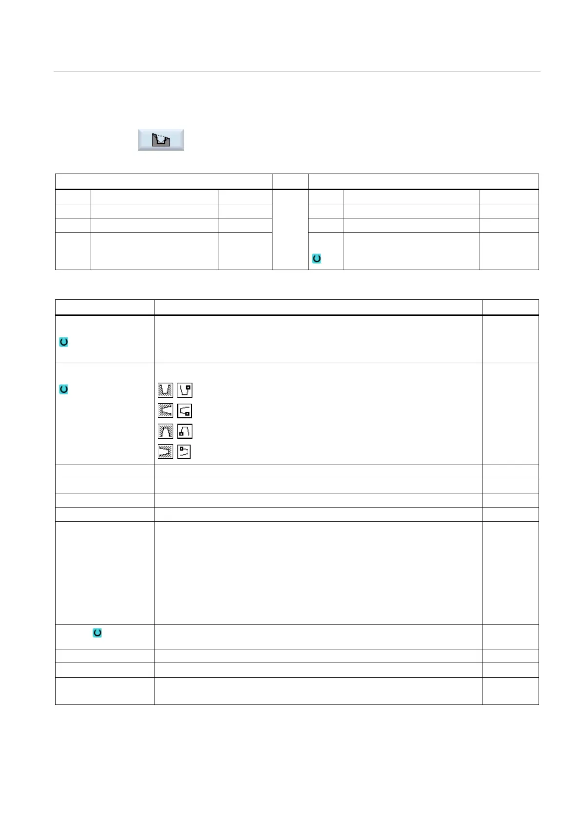
Groove cycle on an incline with inclines, radii or chamfers.
The "Groove 3" input window opens.
Parameters, G code program Parameters, ShopTurn program
PL Machining plane T Tool name
SC Safety clearance mm D Cutting edge number
F Feedrate * F Feedrate mm/rev
S / V
Spindle speed or constant
cutting rate
rpm
m/min
Parameter Description Unit
Machining
• ∇ (roughing)
• ∇∇∇ (finishing)
• ∇ + ∇∇∇ (roughing and finishing)
Position
Groove position:
X0 Reference point in X ∅ mm
Z0 Reference point in Z mm
B1 Groove width mm
T1 Groove depth ∅ (abs) or groove depth referred to X0 or Z0 (inc) mm
D
• Maximum depth infeed for insertion – (only for ∇ and ∇ + ∇∇∇)
• For zero: Insertion in a cut – (only for ∇ and ∇ + ∇∇∇)
D = 0: 1. cut is made directly to final depth T1
D > 0: 1st and 2nd cuts are made alternately to infeed depth D, in order to achieve
a better chip flow and prevent the tool from breaking, refer to
approaching/retraction when roughing.
Alternate cutting is not possible if the tool can only reach the groove base at one
position.
mm
UX or U Finishing allowance in X or finishing allowance in X and Z – (only for ∇ and ∇ +
∇∇∇)
mm
UZ Finishing allowance in Z – (for UX, only for ∇ and ∇ + ∇∇∇) mm
N Number of grooves (N = 1....65535)
DP Distance between grooves (inc)
DP is not displayed when N = 1
mm