Programming technology functions (cycles)
9.2 Rotate
Turning
360 Operating Manual, 01/2015, 6FC5398-8CP40-5BA2
Parameters, G code program
Parameters, ShopTurn program
SC Safety clearance mm D Cutting edge number
S / V
Spindle speed or constant cutting
rate
rpm
m/min
Machining
• ∇ (roughing)
• ∇∇∇ (finishing)
• ∇ + ∇∇∇ (roughing and finishing)
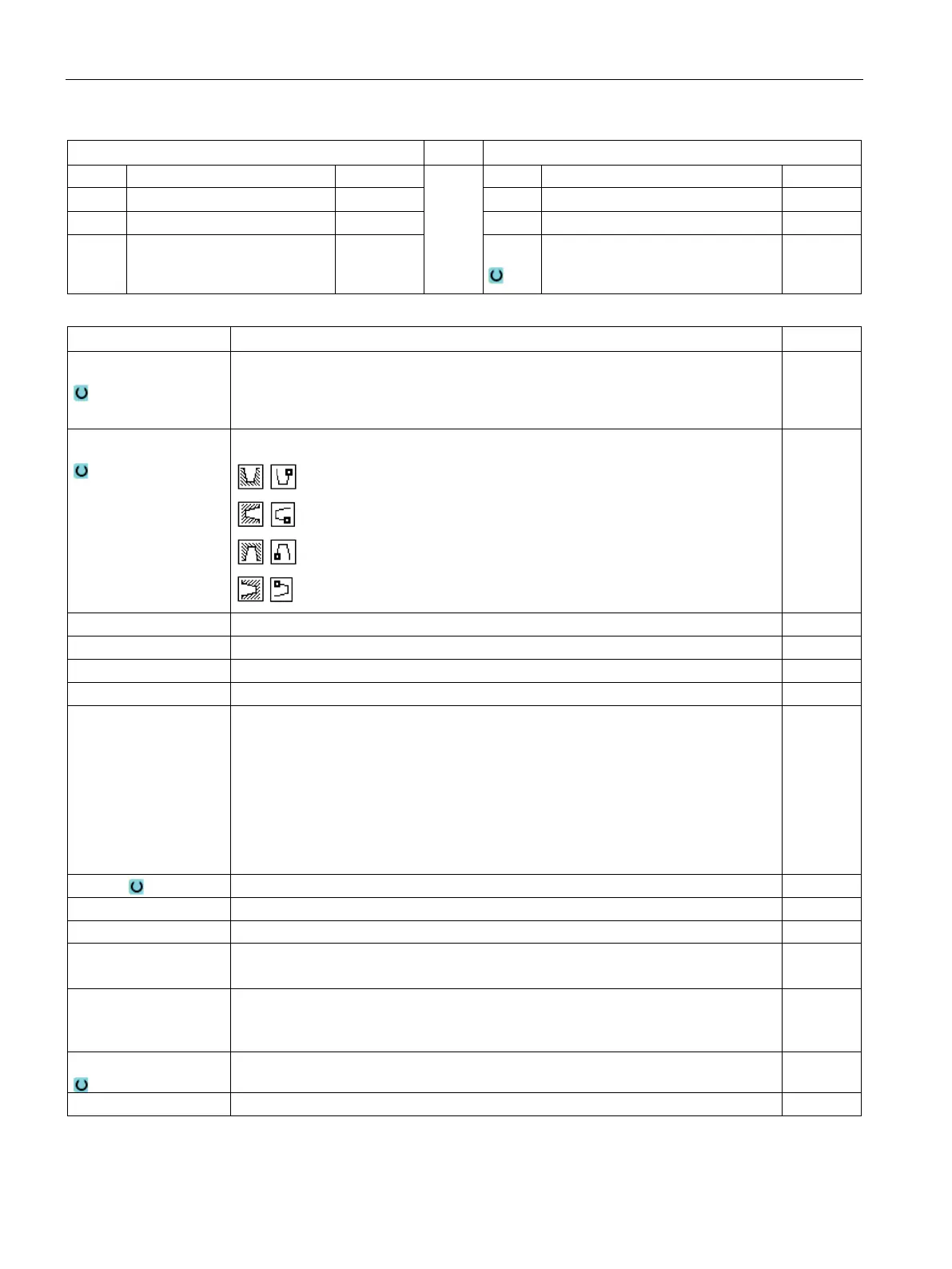
Position
Groove position:
Groove depth ∅ (abs) or groove depth referred to X0 or Z0 (inc)
D
• Maximum depth infeed for insertion – (only for ∇ and ∇ + ∇∇∇)
• For zero: Insertion in a cut – (only for ∇ and ∇ + ∇∇∇)
D = 0: 1. cut is made directly to final depth T1
D > 0: 1st and 2nd cuts are made alternately to infeed depth D, in order to achieve a
better chip flow and prevent the tool from breaking, refer to approaching/retraction
when roughing.
Alternate cutting is not possible if the tool can only reach the groove base at one
mm
Finishing allowance in X or finishing allowance in X and Z – (only for ∇ and ∇ + ∇∇∇)
Finishing allowance in Z – (for UX, only for ∇ and ∇ + ∇∇∇)
Number of grooves (N = 1....65535)
DP Distance between grooves (inc)
DP is not displayed when N = 1
mm
α1, α2 Flank angle 1 or flank angle 2 - (only for grooves 2 and 3)
Asymmetric grooves can be described by separate angles. The angles can be be-
Degrees
FS1...FS4 or R1...R4
Chamfer width (FS1...FS4) or rounding radius (R1...R4) - (only for grooves 2 and 3) mm
Angle of the incline – (only for groove 3)
* Unit of feedrate as programmed before the cycle call