Programming technology functions (cycles)
9.5 Contour milling
Turning
Operating Manual, 01/2015, 6FC5398-8CP40-5BA2
521
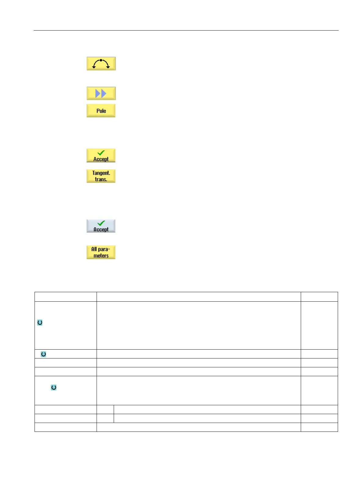
The "Circle" input window opens.
The "Pole Input" input window opens.
Enter all the data available from the workpiece drawing in the input
screen (e.g. length of straight line, target position, transition to next
element, angle of lead, etc.).
Press the "Accept" softkey.
The contour element is added to the contour.
When entering data for a contour element, you can program the trans
i-
tion to the preceding element as a tangent.
nt to prec. elem." softkey. The angle to the preceding
element α2 is set to 0°. The "tangential" selection appears in the p
a-
Repeat the procedure until the contour is complete.
Press the "Accept" softkey.
The programmed contour is transferred to the machining plan (program
view).
If you want to display further parameters for certain contour elements,
e.g. to enter additional commands, press the "All p
arameters" softkey.
Contour element "Straight line, e.g. X"
Machining
surface
(only for ShopTurn)
• Face C
• Face Y
• Face B
• Peripheral surface C
• Peripheral surface Y
Starting angle e.g. to the X axis
Angle to the preceding element
Transition to next ele-
ment
Type of transition
• Radius
• Chamfer
Transition to following element - radius
Transition to following element - chamfer
Additional G code commands