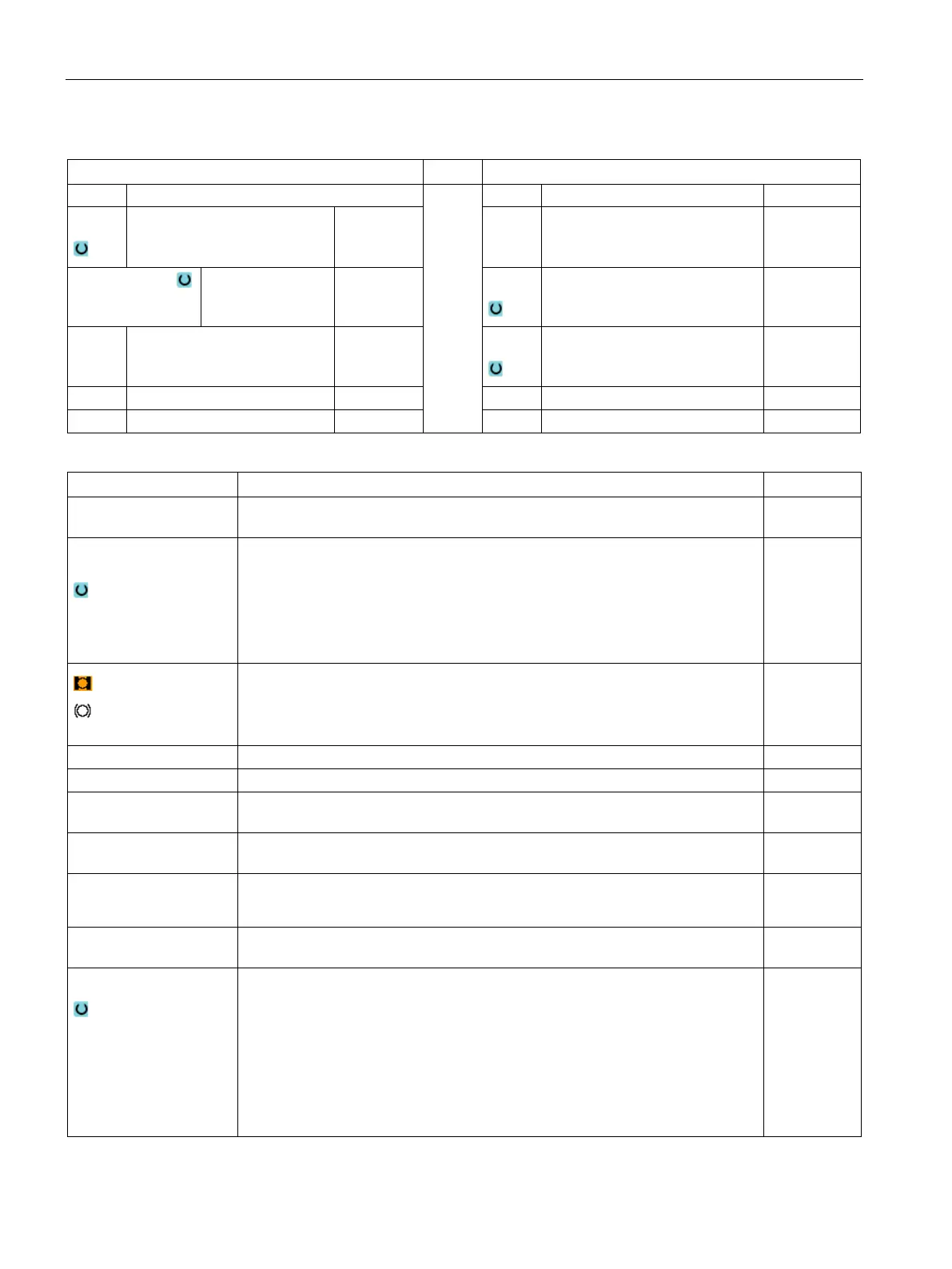
Programming technology functions (cycles)
9.5 Contour milling
Turning
536 Operating Manual, 01/2015, 6FC5398-8CP40-5BA2
Parameters, G code program
Parameters, ShopTurn program
Name of the program to be generated
PL
Machining plane D Cutting edge number
Milling direction
• Climbing
• Conventional
F
Feedrate mm/min
mm/tooth
RP Retraction plane mm S / V
Spindle speed or constant cut-
ting rate
rpm
m/min
TR Reference tool Tool, which is used in the "stock removal" machining step. This is
used to determine the plunge position.
Machining
surface
(only for ShopTurn)
• Face C
• End face Y (only when Y axis exists)
• Face B
• Peripheral surface C
• Peripheral surface Y (only when Y axis exists)
Clamp/release spindle (only for end face Y/B and peripheral surface Y)
The function must be set up by the machine manufacturer.
Reference point in the tool axis Z
Pocket depth ∅ (abs) or depth referred to Z0
CP Positioning angle for machining area
- (only for ShopTurn, machining surface, face Y)
Degrees
C0 Positioning angle for machining surface
- (only for ShopTurn, machining surface, peripheral surface Y)
Degrees
DXY
• Maximum plane infeed
• Maximum plane infeed as a percentage of the milling cutter diameter
mm
%
UXY Finishing allowance, plane
mm
Lift mode
Lift mode before new infeed
If the machining operation requires several points of insertion, the retraction
height can be programmed:
• To retraction plane
• Z0 + safety clearance
When making the transition to the next insertion point, the tool returns to this
height. If there are no elements larger than Z0 in the pocket area, Z0 + safety
clearance" can be selected as the lift mode.
mm
mm

 Loading...


