How to use this manual
0-6
How to use this manual
Manual format
The format of this manual has been designed to make service procedures clear and easy to under-
stand. Use the following information as a guide for effective and quality service.
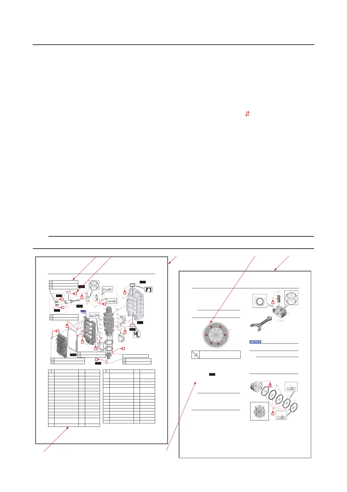
• Parts are shown and detailed in an exploded diagram and are listed in the component list (see “1”
in the following figure for an example page).
• The component list consists of the basic removal or disassembly order (“ ”), part names, quanti-
ties, and remarks, which indicate the bolt and screw dimensions and other information (see “2” in
the following figure). For the installation or assembly procedure, reverse the order.
• Symbols are used to indicate important aspects of a procedure, such as the grade of lubricant and
the lubrication points (see “3” in the following figure).
• Tightening torque specifications are provided in the exploded diagrams (see “4” in the following fig-
ure), and in the related detailed instructions. Some torque specifications are listed in stages as
torque values or angles in degrees.
• Separate procedures and illustrations are used to explain the details of removal, checking, and in-
stallation where necessary (see “5” in the following figure for an example page). Detailed explana-
tions of the procedures are expressed by using lower case letters such as a, b, c, .... (see “6” in the
following figure).
• Numbers enclosed in brackets are used to indicate the removal or tightening order of bolts, screws,
and other parts (see “7” in the following figure).
For troubleshooting procedures, see Chapter 4, “Troubleshooting”.
7-92
Cylinder block
Assembling the cylinder block
1. Install:
•Dowel
•Pickup rotor
•Drive gear
Tighten the drive gear bolts “1” to the speci-
fied torque in the order [1], [2], and so on.
2. Assemble:
•Piston
• Connecting rod
• Piston pin
•Piston clips
• Piston rings
a. Assemble the piston “1”, connecting
rod “2”, piston pin “3”, and new piston
pin clips “4”.
• Face the mark “a” on the connecting rod “2”
in the same direction as the mark “b” on the
piston crown.
• Make sure that the clip “4” end is not aligned
with the groove “c” in the piston pin boss.
b. Install the oil rings “1”, 2nd ring “2”,
and top ring “3”.
Do not scratch the pistons or break the pis-
ton rings.
• Make sure that the “2R” mark “a” on the 2nd
ring “2” and “1R” mark “b” on the top ring
“3” are facing up.
• Make sure that the piston rings move
smoothly.
c. Offset the piston ring end gaps.
3. Install:
• Crankshaft journal bearings (cylinder
block side) “1”
Drive gear bolt “1”
10 N·m (1.0 kgf·m, 7.4 lb·ft)
[5][5]
[2][2]
[4][4]
[6][6]
[1][1]
[3][3]
[5][5]
[2][2]
[4][4]
[6][6]
[1][1]
[3][3]
[5][5]
[2][2]
[4][4]
[6][6]
[1][1]
[3][3]
1
#3
#4
#5
#1
#2
#3
#4
#5
#1
#2
45˚ 45˚
1
2
3
a
b
EE
Cylinder block
7-77
Cylinder block
EE
EE
EE
EE
EE
EE
EE
EE
EE
EE
EE
EE
EE
3
4
5
6
8
7
9
10
6
New
15
14
17
17
New
11
20
21
22
19
18
15
New
12
13
New
25
26
16
27
New
24
New
25
28
New
23
New
1
2
30
31
32
29
New
14 N
·
m (1.4 kgf
·
m, 10 lb
·ft
)
27.5 N
·
m (2.75 kgf
·
m, 20.28 lb
·ft
)
40 N
·
m (4.0 kgf
·
m, 30 lb
·ft
)
90°
40 N
·
m (4.0 kgf
·
m, 30 lb
·ft
)
90°
13 N
·
m (1.3 kgf
·
m, 9.6 lb
·ft
)
28 N
·
m (2.8 kgf
·
m, 21 lb
·ft
)
90°
1
2
3
14 N
·
m (1.4 kgf
·
m, 10 lb
·ft
)
28 N
·
m (2.8 kgf
·
m, 21 lb
·ft
)
1
2
1
2
1
2
1
2
10 N
·
m (1.0 kgf
·
m, 7.4 lb
·ft
)
Part name
Q
’ty
Remarks
1Bolt M10
× 50 mm 8
2Flange 1
3 Bolt M8
× 50 mm 26
4 Crankcase cover 1
5Gasket 1
6Dowel 2
7 Bolt M8
× 50 mm 10
8 Bolt M8
× 70 mm 6
9Bolt M10
× 103 mm 20
10 Crankcase 1
11 O-ring 1
12 Thrust bearing 1
13 Thrust bearing 1
14 Dowel 10
15 Bolt M9
× 42mm 16
16
Connecting rod as-
sembly
8
17 Crankshaft pin bearing 16
18
Crankshaft journal
bearing
5
19 Crankshaft 1
20 Thrust bearing 1
21 Thrust bearing 1
22
Crankshaft journal
bearing
5
23 Oil seal 1
24 Oil seal 1
25 Clip 16
26 Piston pin 8
27 Piston ring set 8
28 Piston 8
29 Bolt M6
× 14 mm 6
30 Drive gear 1
31 Pickup rotor 1
32 Dowel 1
Part name
Q
’ty
Remarks
26