7-66
Cylinder head
Do not get the lapping compound on the
valve stem and valve guide.
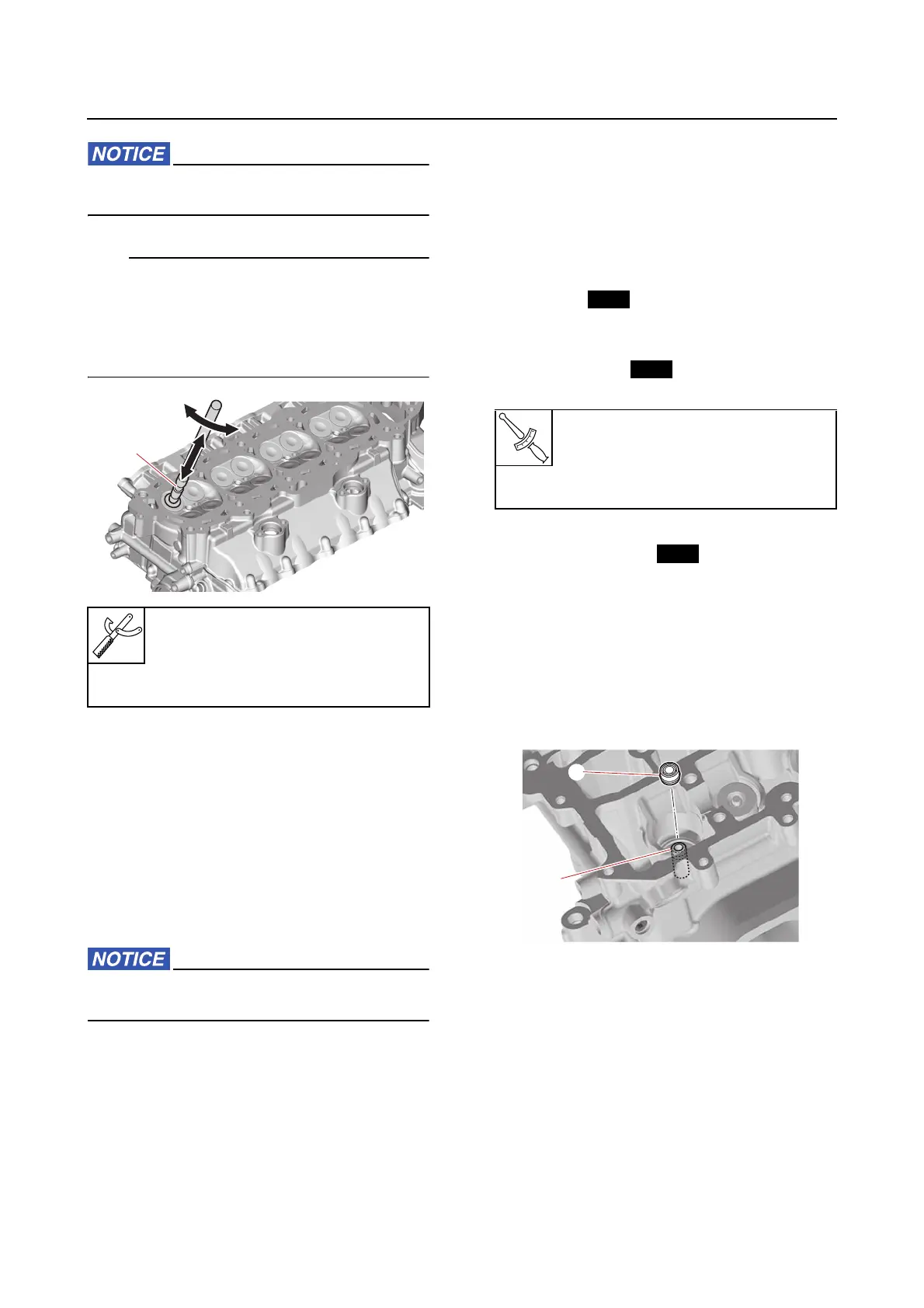
After refacing the contact width of the valve
seat to specification, apply a thin, even layer of
lapping compound onto the valve seat, and
then lap the valve using the special service
tool “1”.
3. Measure:
• Valve seat contact width
See step 2 in “Checking the valve seat”
(7-63).
Checking the cylinder head anode
1. Check:
•Anode
Eroded (1/2 or more worn out) → Replace.
Adhered grease, oil, or scales → Clean.
Do not apply grease, oil, or paint to the an-
odes.
Checking the cam position sensor
1. Check:
• Electrical performance
See “Checking the cam position sensor”
(5-23).
Checking the OCV
1. Check:
• Electrical performance
See “Checking the OCV” (5-25).
Assembling the cylinder head
1. Install:
•O-rings
•Plugs
•Cam position sensors
•OCV gaskets
• OCV assemblies
2. Install:
• Valve stem seals
• Exhaust valves
• Intake valves
• Spring seats
• Valve springs
• Spring retainers
• Valve cotters
a. Install a new valve seal “1” onto the
valve guide “2”.
b. Install the valve “1”, valve spring seat
“2”, valve spring “3”, and valve spring
retainer “4” in this order, and then in-
stall the special service tools.
Valve lapper “1”
90890-04101
Valve lapping tool “1”
YM-A8998
Plug
25 N·m (2.5 kgf·m, 18 lb·ft)
OCV bolt
6.5 N·m (0.65 kgf·m, 4.8 lb·ft)