5-29
Fuel control unit and component
f. Install the fuel filter assembly. See “Fu-
el filter assembly” (6-3).
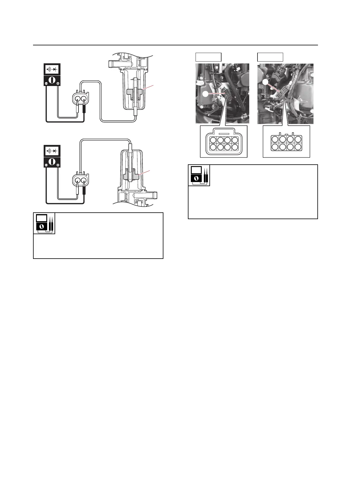
g. Connect the water detection switch
coupler.
Checking the fuel injector
1. Check:
• Fuel injector
a. Check the operation of the fuel injector
using the YDIS “Stationary test” and
check the operating sound.
b. Disconnect the fuel injector sub-wire
harness couplers “a”.
c. Measure the fuel injector resistance.
Out of specification → Replace the fuel
injector.
d. Connect the fuel injector sub-wire har-
ness couplers.
Checking the low-pressure fuel pump
and high-pressure fuel pump
1. Check:
• Low-pressure fuel pump
• High-pressure fuel pump
a. Check the operation of the low-pres-
sure fuel pump and high-pressure fuel
pump using the YDIS “Stationary test”
and check the operating sound.
b. Disconnect the high-pressure fuel
pump couplers “a” and “b”.
c. Connect the tester probes to the termi-
nals of the high-pressure fuel pump
couplers, and then measure the input
voltage.
Water detection switch continuity
No continuity
Float position “A”
Continuity
Float position “B”
Resistance (reference data)
1.74–2.04 Ω
Fuel injector #1, #2 terminal 4–8
Fuel injector #3, #4 terminal 3–7
Fuel injector #5, #6 terminal 2–6
Fuel injector #7, #8 terminal 1–5
1
1
5
2
6
3
7
4
8
5
2
6
3
7
4
8
PORT
STBD
a
a