Fuel control unit and component
5-28
Fuel control unit and component
Checking the injector driver circuit
1. Remove:
• Intake manifold (PORT)
See “Intake manifold” (6-24).
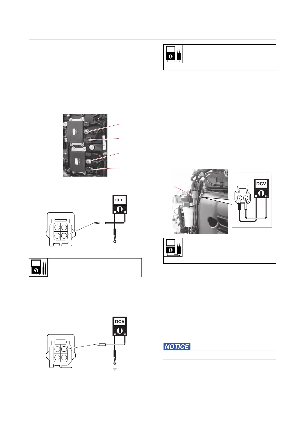
2. Check:
• Injector driver
a. Disconnect the injector driver couplers
“a” and “b”.
b. Check the wire harness for continuity.
c. Turn the main switch or power switch
to ON, and then measure the input volt-
age between the injector driver coupler
terminal 1 and ground.
d. Turn the main switch or power switch
to OFF.
e. Connect the injector driver couplers.
Checking the water detection switch
1. Check:
• Water detection switch
a. Disconnect the water detection switch
coupler “a”.
b. Turn the main switch or power switch
to ON, and then measure the input volt-
age at the water detection switch cou-
pler.
c. Turn the main switch or power switch
to OFF, and then remove the fuel filter
assembly.
d. Check that the float “1” moves
smoothly.
e. Check the water detection switch for
continuity when the float “1” is in posi-
tions “A” and “B”.
Out of specification → Replace the fuel
cup assembly.
Do not remove the clip and float.
Wire harness continuity
Terminal 3–Ground
Input voltage
12 V
Terminal 1–Ground
Input voltage
5 V
Blue/White (L/W)–Black (B)