Ignition unit and component
5-38
c. Turn the main switch or power switch
to OFF.
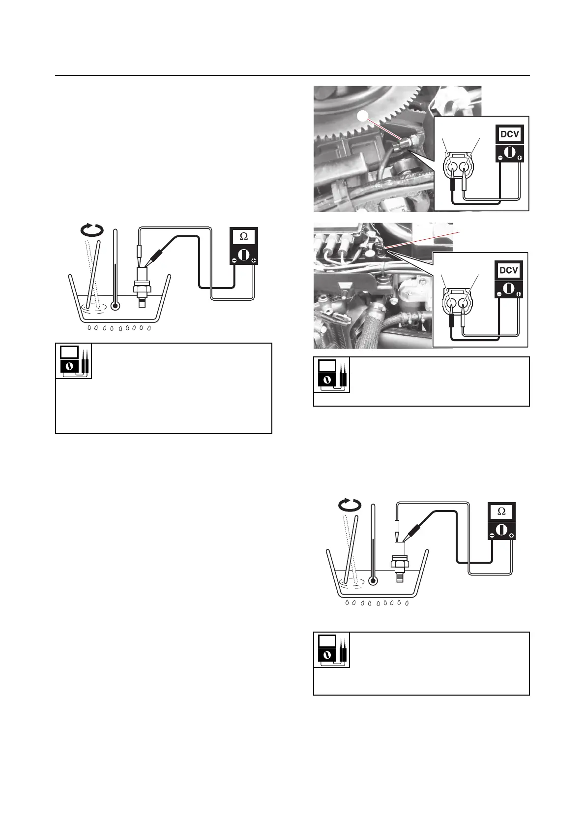
d. Remove the engine temperature sen-
sor.
e. Place the engine temperature sensor in
a container of water and heat the water
slowly.
f. Measure the engine temperature sen-
sor resistance.
g. Install the engine temperature sensor
and connect the coupler.
Checking the thermo sensor
1. Remove:
•Shroud cover
• Terminal covers
See “Shroud cover and terminal cover”
(7-5).
2. Check:
• Thermo sensor
a. Disconnect the thermo sensor cou-
plers “a”.
b. Turn the main switch or power switch
to ON, and then measure the input volt-
age at the thermo sensors coupler.
c. Turn the main switch or power switch
to OFF.
d. Remove the thermo sensors.
e. Place the thermo sensors in a contain-
er of water and heat the water slowly.
f. Measure the thermo sensor resistance.
g. Install the thermo sensors and connect
the couplers.
See “Shroud cover and terminal cover”
(7-5).
Resistance at 20 °C (68 °F) (refer-
ence data)
2.51–2.77 kΩ
Resistance at 100 °C (212 °F) (ref-
erence data)
0.21–0.22 kΩ
Input voltage
5 V
Black/Yellow (B/Y)–Black (B)
Resistance at 20 °C (68 °F)
2.25–2.65 kΩ
Resistance at 80 °C (176 °F)
0.31-0.33 kΩ