Power unit (check and adjustment)
7-3
See “Direct injection pump and fuel injec-
tor” (6-18).
• Spark plug
• Ignition coil
See “Ignition coil and spark plug” (7-40).
• Exhaust joint
See “Installing the exhaust joint” (7-12)
and “Installing the exhaust joint assembly”
(7-8).
• Fuel rail cover
See “Fuel hose assembly” (6-12).
• Electrical management box
See “Installing the electrical management
box” (7-23).
• Shroud cover and terminal cover
See “Shroud cover and terminal cover”
(7-5).
• Bottom cowling
See “Bottom cowling (PORT and STBD)”
(9-3).
• Bottom cowling cover
See “Bottom cowling cover and apron
cover” (9-1).
Adjusting the valve clearance
Adjust the valve clearances when the engine is
cold.
• Do not turn the flywheel magneto coun-
terclockwise. Otherwise, the water pump
impeller could be damaged.
• Do not turn the flywheel magneto, VCT
assembly or driven sprocket when the
timing belt is not installed. Otherwise, the
pistons and valves, or intake and exhaust
valves will collide with each other and be
damaged.
1. Remove:
• Fuel hose assembly
See “Fuel hose assembly” (6-12).
• Intake manifold (PORT)
See “Intake manifold” (6-24).
• Flywheel magneto
See “Removing the flywheel magneto”
(7-25).
• Timing belt
See “Removing the timing belt” (7-43).
• Chain tensioner
• Camshaft
(with driven sprocket and VCT assembly)
• Valve lifter
See “Removing the camshaft, VCT as-
sembly, and driven sprocket” (7-48).
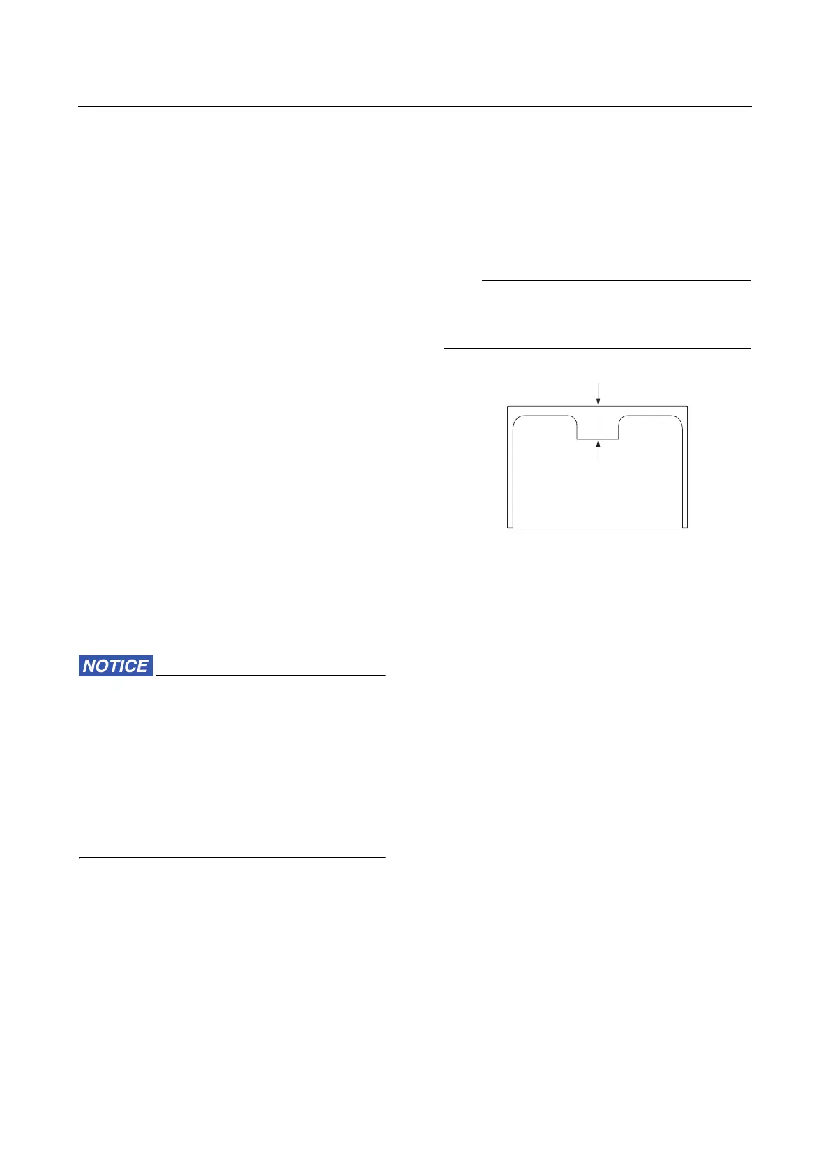
2. Measure:
• Valve lifter thickness “a”
• Make sure to keep the parts in the order of
removal.
• Write down the measurement data.
3. Select:
• Valve lifter
a. Select the necessary valve lifter by cal-
culating its thickness using the follow-
ing formula.
Calculation formula:
Necessary valve lifter thickness =
Removed valve lifter thickness +
Measured valve clearance –
Specified valve clearance
Removed valve lifter thickness = 3.000
mm
Measured valve clearance = 0.255 mm
Specified valve clearance = 0.205 mm
Necessary valve lifter thickness
= 3.000 mm + 0.255 mm – 0.205 mm
= 3.050 mm
4. Install:
• Valve lifter
• Camshaft
• Chain tensioner
See “Installing the camshaft, VCT assem-
bly, and driven sprocket” (7-53).
• Timing belt
See “Installing the timing belt” (7-43).