7-38
ECM, injector driver, and rectifier/regulator
Removing the rectifier/regulator
1. Remove:
• Low-pressure fuel pump
See “Low-pressure fuel pump” (6-6).
• Vapor separator assembly
See “Removing the vapor separator”
(6-10).
• Surge tank
See “ETV” (6-28).
Checking the rectifier/regulator
anode
1. Check:
•Anode
Eroded (1/2 or more worn out) → Replace.
Adhered grease, oil, or scales → Clean.
Do not apply grease, oil, or paint to the an-
odes.
Installing the ECM and injector driver
1. Install:
• Holder bracket
•Grommets
•Collars
• ECM/injector driver bracket
•Coupler bracket
• Low-pressure fuel pump relay
• Injector drivers
•ECM
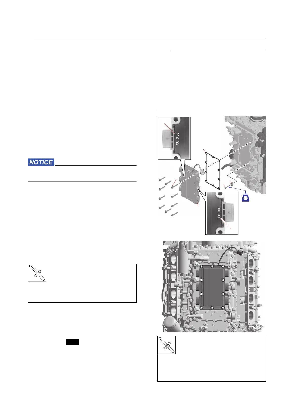
Installing the rectifier/regulator
1. Install:
• Rectifier/regulator anode “1”
• Rectifier/regulator anode screw “2”
•Gasket “3”
• Rectifier/regulator “4”
• Rectifier/regulator bolts “5”
• Install the rectifier/regulator “4” so that its
side with the “OUTSIDE” mark “a” is facing
outward.
• Tighten the rectifier/regulator bolts “5” to the
specified torques in 2 stages and in the order
[1], [2], and so on.
• The rectifier/regulator shown is for F450A/
FL450A/XF450.
Coupler bracket screw
2.5 N·m (0.25 kgf·m, 1.8 lb·ft)
Low-pressure fuel pump relay
screw
2.5 N·m (0.25 kgf·m, 1.8 lb·ft)
Rectifier/regulator anode screw
“2”
3.9 N·m (0.39 kgf·m, 2.9 lb·ft)
Rectifier/regulator bolts “5”
1st: 14 N·m (1.4 kgf·m, 10 lb·ft)
2nd: 28 N·m (2.8 kgf·m, 21 lb·ft)
[4][4][4]
[2][2][2]
[7][7][7]
[6][6][6]
[10][10][10]
[4][4] [3][3][3]
[1][1][1]
[8][8][8]
[5][5][5]
[9][9][9]
[3][3]
[1][1] [2][2]
[8][8]
[7][7]
[6][6]
[10][10]
[5][5]
[9][9]