Wire harness
7-33
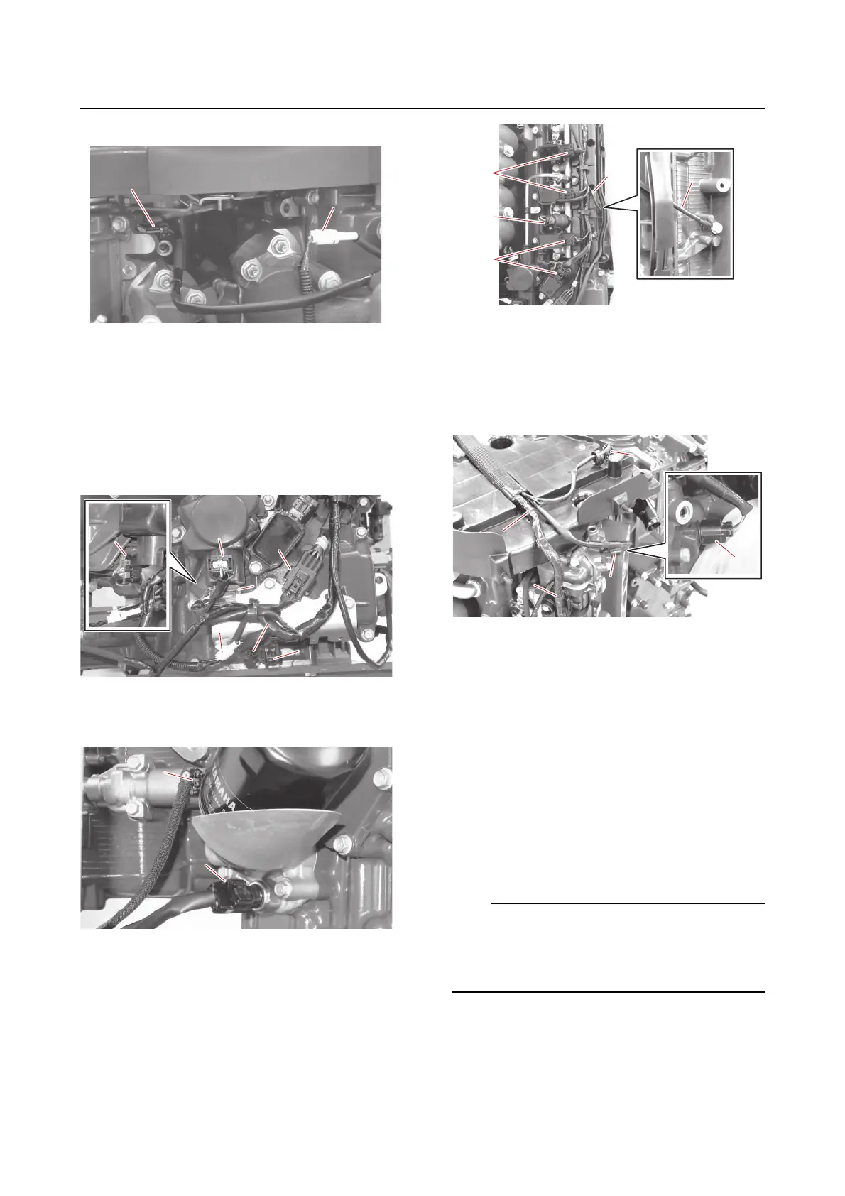
• Knock sensor coupler (upper) “b”
12. Disconnect:
• Direct injection pump coupler (STBD) “a”
• Sub-wire harness coupler (STBD) “b”
• Joint connector “c”
(from the bracket)
• Knock sensor coupler (lower) “d”
• SCU coupler “e”, “f”
(from the bracket)
13. Disconnect:
• Oil pressure sensor coupler “a”
•OCV coupler (STBD) “b”
14. Disconnect:
• Ground lead “a”
• Ignition coil coupler (STBD) “b”
• Fuel pressure sensor (direct injection
pump) coupler (STBD) “c”
15. Disconnect:
• Wire harness “a”
(from the guides)
• Cam position sensor coupler (STBD IN)
“b”
• Thermo sensor coupler (STBD) “c”
Installing the wire harness
Route the wire harness.
See “Electrical component and wire harness
routing” (5-1).
1. Connect:
•Holder “1”
• Wire harness “a”
(to the guides)
•O-ring “2”
• Cam position sensor coupler (STBD IN)
“b”
• Thermo sensor coupler (STBD) “c”
Check that the O-ring “2” is inserted between
the cam position sensor “3” and the cam po-
sition sensor coupler “b”. See “Electrical com-
ponent and wire harness routing” (5-1).