7-34
Wire harness
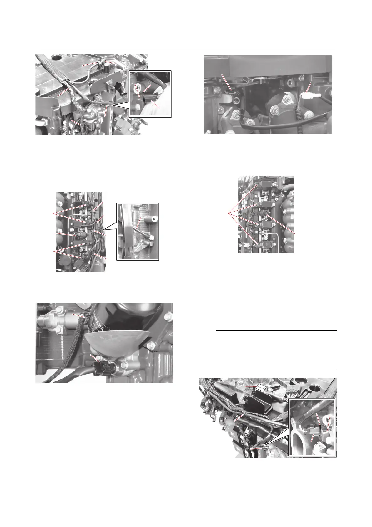
2. Connect:
•Holder “1”
• Ground lead “a”
• Ignition coil coupler (STBD) “b”
• Fuel pressure sensor (direct injection
pump) coupler (STBD) “c”
3. Connect:
• Oil pressure sensor coupler “a”
•OCV coupler (STBD) “b”
4. Connect:
• Cam position sensor coupler (PORT EX)
“a”
• Knock sensor coupler (upper) “b”
5. Connect:
• Ignition coil coupler (PORT) “a”
• Fuel pressure sensor (direct injection
pump) coupler (PORT) “b”
6. Connect:
• Wire harness “a”
(to the guide)
•O-ring “1”
• Cam position sensor coupler (PORT IN)
“b”
• Joint connector “c”
Check that the O-ring “1” is inserted between
the cam position sensor “2” and the cam po-
sition sensor coupler “b”. See “Electrical com-
ponent and wire harness routing” (5-1).
7. Connect:
•Holder “1”
• Engine temperature sensor coupler “a”