Wire harness
7-35
• Injector driver coupler “b”, “c”, “d”
• PTT buzzer coupler “e”
Fit the injector driver coupler “d” onto the in-
jector driver, and then move the lock lever “f”
in the direction shown to engage the coupler.
Make sure that the tab “g” is securely locked
in place.
8. Connect:
• Ground lead “a”, “b”
•OCV coupler (PORT) “c”
9. Connect:
• PTT sensor coupler “a”
(to the bracket)
• Sub-wire harness coupler (PORT) “b”
• Direct injection pump coupler (PORT) “c”
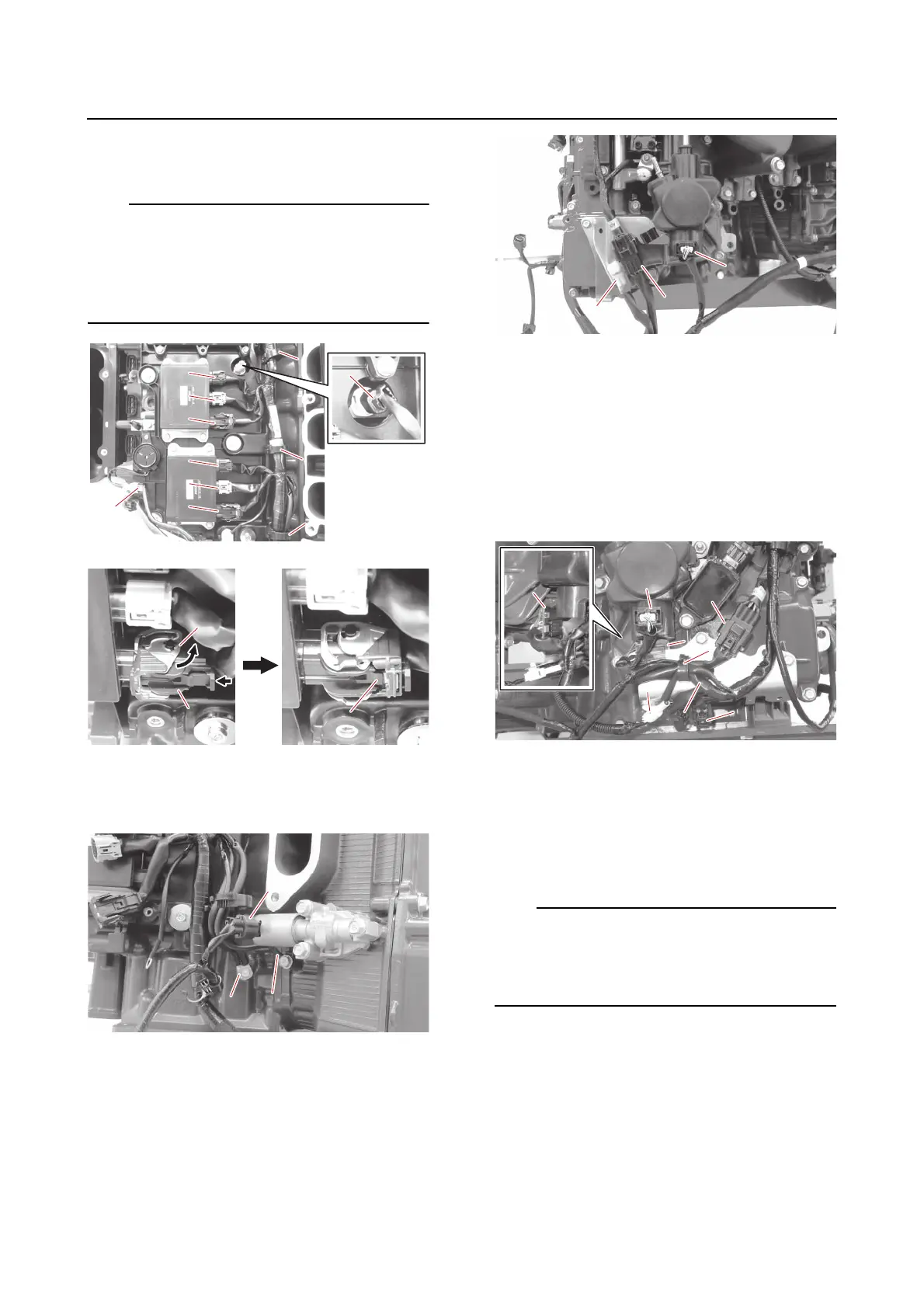
10. Connect:
•Holder “1”
• SCU coupler “a”, “b”
(to the bracket)
• Knock sensor coupler (lower) “c”
• Joint connector “d”
(to the bracket)
• Sub-wire harness coupler (STBD) “e”
• Direct injection pump coupler (STBD) “f”
11. Connect:
•Holder “1”
• ECM coupler “a”, “b”, “c”
• Thermo sensor coupler (PORT) “d”
• Wire harness “e”
(to the bracket)
Fit the ECM coupler onto the ECM, and then
move the lock lever “f” in the direction shown
to engage the coupler. Make sure that the tab
“g” is securely locked in place.