Charging unit and component
5-34
Charging unit and component
Checking the lighting coil (stator
assembly)
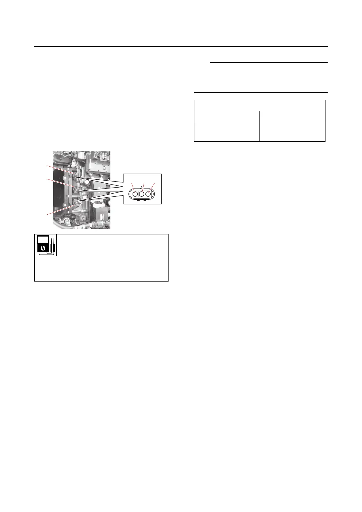
1. Check:
• Lighting coil
a. Remove the intake manifold (PORT).
See “Intake manifold” (6-24).
b. Disconnect the lighting coil couplers
“a”, “b” and “c”.
c. Measure the lighting coil resistance at
each coupler.
d. Connect the lighting coil couplers.
e. Install the intake manifold (PORT).
See “Intake manifold” (6-24).
Checking the rectifier/regulator
1. Check:
• Rectifier/regulator (trigger leads)
a. Connect the YDIS to display “Battery
voltage” and “Accessory battery volt-
age”.
b. Start the engine, and measure the bat-
tery charging voltages.
Engine battery charging voltage is out
of specification → Check the lighting
coil and rectifier/regulator continuity.
House battery (accessory battery)
charging voltage is low → Replace the
rectifier/regulator.
When the battery is fully charged, the voltage
value at low engine speed may fluctuate due
to the influence of voltage control.
c. Turn the main switch or power switch
to OFF.
2. Remove:
• Intake manifolds
See “Intake manifold” (6-24).
• Surge tank
See “ETV” (6-28).
3. Check:
• Rectifier/regulator continuity
Out of specification → Replace the rectifi-
er/regulator.
a. Disconnect the rectifier/regulator cou-
plers.
b. Set the digital circuit tester to the diode
mode.
c. Check the rectifier/regulator for conti-
nuity.
See “Rectifier/regulator continuity ta-
ble (F400A/FL400A/XF400A)” (A-20) or
“Rectifier/regulator continuity table
(F450A/FL450A/XF450A)” (A-22).
Resistance (reference data)
0.0904–0.1356 Ω
Terminal “d”–Terminal “e”
Terminal “d”–Terminal “f”
Terminal “e”–Terminal “f”
Charging voltage
Engine battery More than 13.0 V
House battery
(Accessory battery)
More than 14.0 V