2-13
Bracket unit
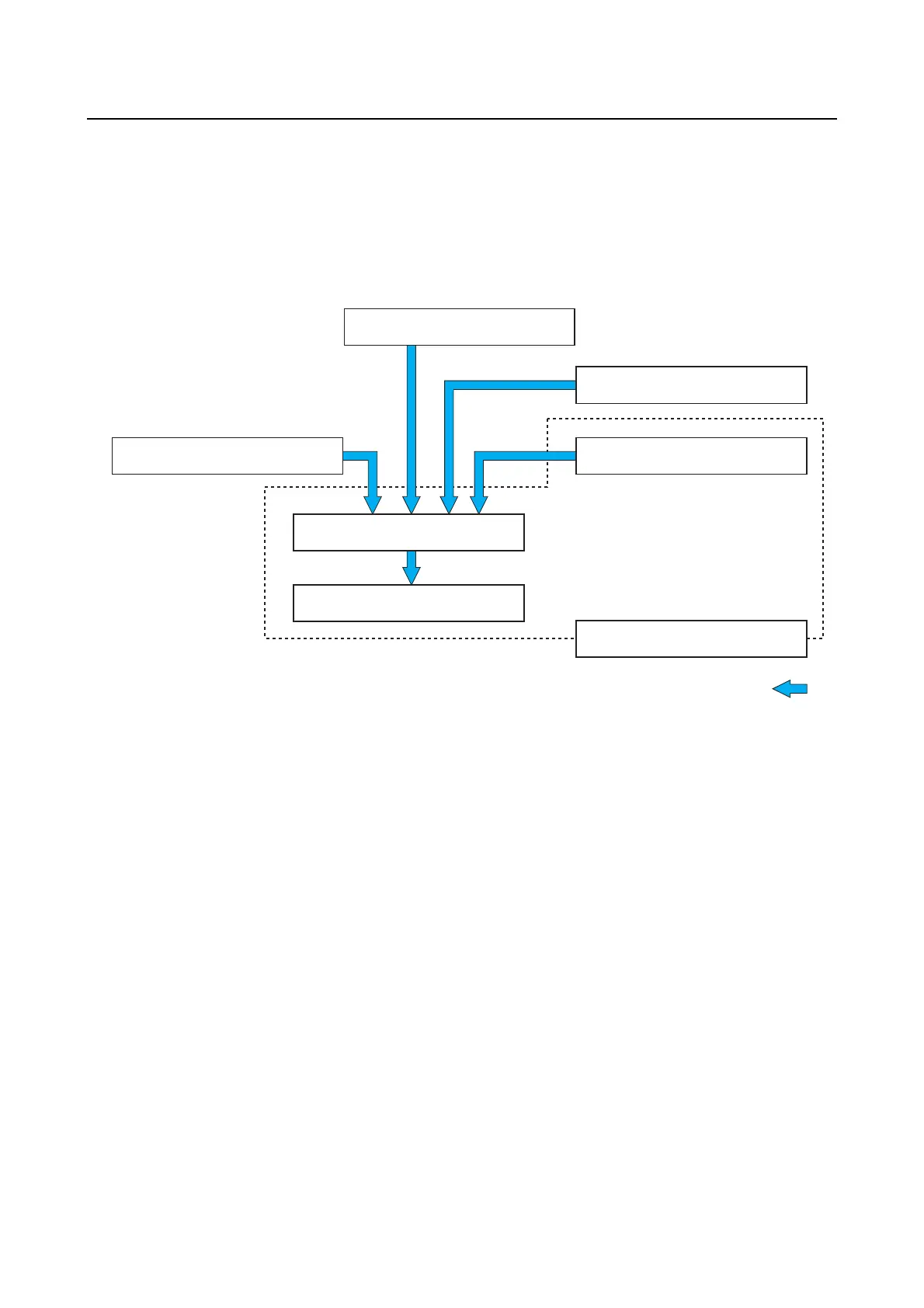
System diagram
When the signals from the steering wheel and joystick are input into the steering control unit (SCU),
the SCU uses that information together with the information from other sensors to calculate the opti-
mal steering control and operates the steering motor to match the intended steering angle of the op-
erator. For multiple engine applications, the system controls the steering angle of each outboard
motor so that the boat moves in the intended direction.
Digital Electronic Control model
A
1. Helm unit
2. Digital Electronic Control
3. Engine ECM
4. Position sensor
5. SCU
6. Steering motor
7. Steering actuator
1. Helm unit
2. Digital Electronic Control
3. Engine ECM
4. Position sensor
5. SCU
6. Steering motor
7. Steering actuator
A. Electronic signal