Fuel hose, feed valve, relief valve, and fuel strainer
6-16
Checking the fuel pressure sensor
(high-pressure fuel pump)
1. Check:
• Electrical performance of the fuel pressure
sensor (high-pressure-fuel pump).
See “Checking the fuel pressure sensor”
(5-32).
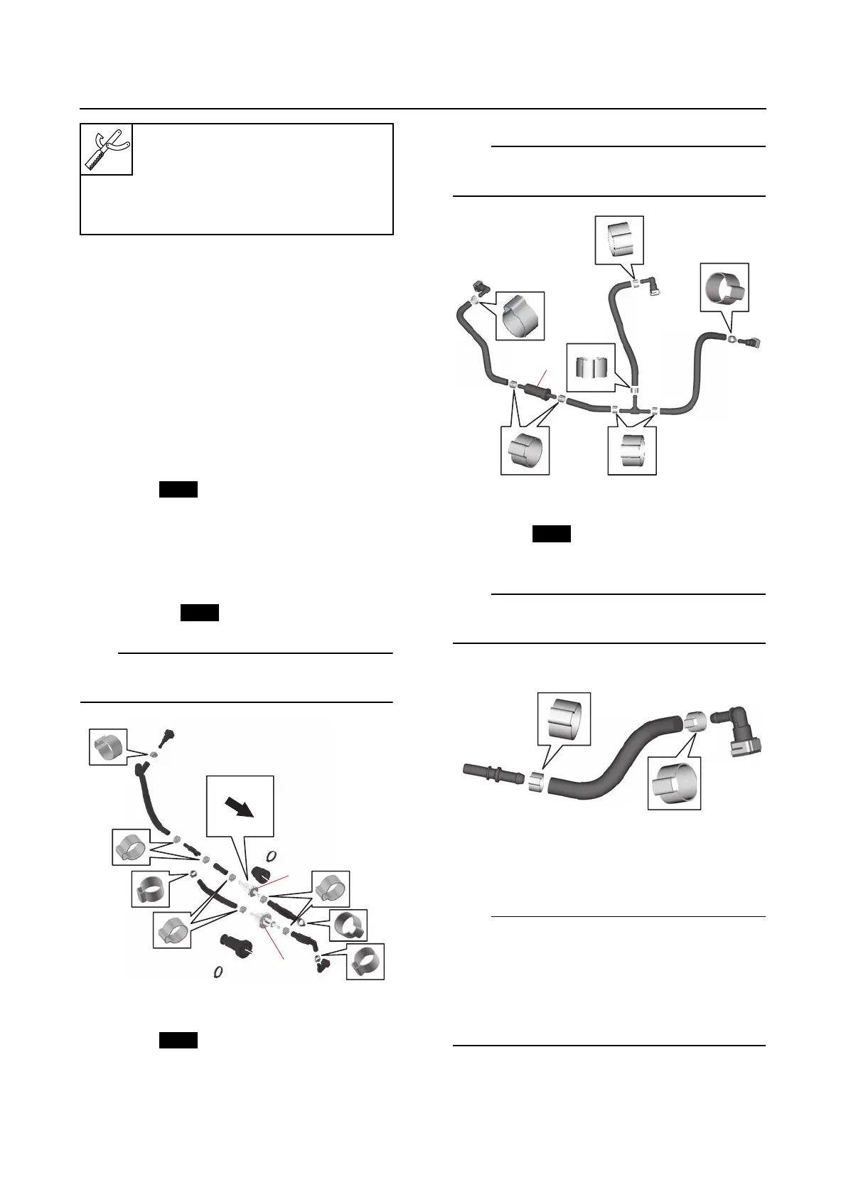
Assembling the fuel hose assembly
1. Assemble:
• Fuel hose
•Clamp
•Joint
• Quick connector
• Relief valve “1”
• Fuel feed valve “2”
•Cover
•Plastic tie
Make sure to face the crimped section of the
clamp in the direction shown in the illustration.
2. Assemble:
• Fuel hose
•Clamp
•Fuel strainer “1”
•Joint
• Quick connector
Make sure to face the crimped section of the
clamp in the direction shown in the illustration.
3. Assemble:
• Fuel hose
•Clamp
•Joint
Make sure to face the crimped section of the
clamp in the direction shown in the illustration.
4. Tighten:
•Clamp “1”
• Push the protrusion “a” on the clamp using
the side “b”, which does not have a slot, of
the tool.
• Make sure that the ends “c” of the clamp are
hooked securely onto the portion “d” of the
clamp.
Vacuum/pressure pump gauge
set “1”
90890-06945
Pressure/vacuum tester “1”
YB-35956-B