Steering unit
5-52
Steering unit
Checking the steering actuator
1. Check:
• Steering actuator
a. Disconnect the engine ECM couplers
“a” and “b”.
b. Disconnect the SCU signal couplers
“c” and “d”.
c. Check the wire harness for continuity.
Continuity between the engine ECM
coupler “a” and the SCU signal coupler
“c”:
Continuity between the engine ECM
coupler “a” and the SCU signal coupler
“d”:
Continuity between the engine ECM
coupler “b” and the SCU signal coupler
“d”:
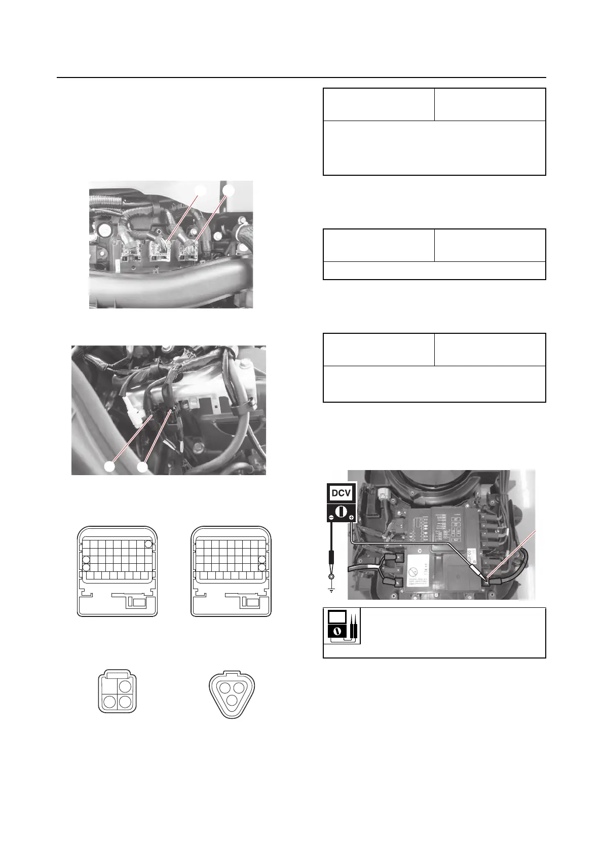
d. Turn the main switch or power switch
to ON, and then measure the input volt-
age between the electrical manage-
ment box terminal “1” and ground.
e. Turn the main switch or power switch
to OFF.
f. Connect the engine ECM couplers and
SCU signal couplers.
17
26
36
1
34
1
2
3
18
9
a
c
b
d
<B> <C>
Terminal of coupler
“a”
Terminal of coupler
“c”
17 – 4
26 – 3
36 – 1
Terminal of coupler
“a”
Terminal of coupler
“d”
36 – 3
Terminal of coupler
“b”
Terminal of coupler
“d”
9–2
18 – 1
Input voltage
12 V
Terminal 1–Ground