A-9
Wiring diagram
Wiring diagram
How to use the wiring diagram
Composition of the wiring diagrams
The wiring diagram consists of five categories: “Engine control unit”, “Fuel unit”, “Ignition unit”,
“Charging unit and starting unit”, and “PTT unit and steering unit”.
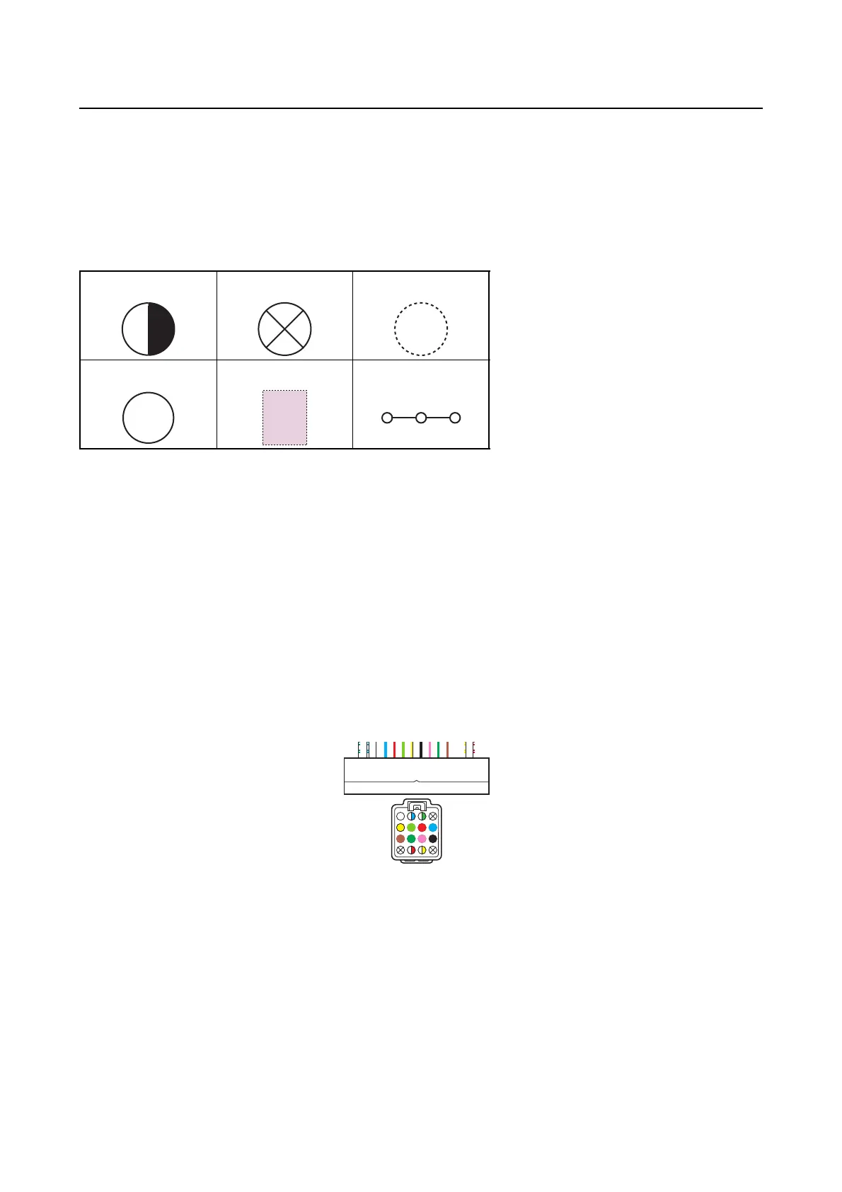
Legend symbols in the wiring diagrams
Terminal numbers
• Terminal numbers are indicated for cases where terminal locations of wires are unclear.
• In the coupler illustrations, only the rightmost and leftmost terminal numbers are indicated, and ter-
minal numbers between them are omitted.
123
456
1. Double-colored wire
2. Not used (vacant)
3. A wire is not included in the selected wiring unit
4. Alert buzzer
5. Optional parts
6. Continuity
BZ
2
3
1
4
5
6
7
8
9
10
11
12
13
14
15
16
4
8
12
16
1
5
9
13