Ignition unit and component
5-36
c. Turn the main switch or power switch
to OFF.
d. Connect the crankshaft position sen-
sor coupler.
Checking the intake air pressure/
temperature sensor
1. Check:
• Intake air pressure/temperature sensor
a. Measure the ambient temperature.
b. Connect the YDIS to display “Intake air
temperature”.
c. Check that the difference between the
ambient temperature and the dis-
played intake air temperature is within
± 5 °C (± 9 °F).
• Check the intake air pressure/temperature
sensor when the engine is cold.
• When checking the intake air pressure/tem-
perature sensor, remove the top cowling and
do not start the engine.
d. Disconnect the intake air pressure/
temperature sensor coupler “a”.
e. Turn the main switch or power switch
to ON, and then measure the input volt-
age at the intake air pressure/tempera-
ture sensor coupler.
f. Turn the main switch or power switch
to OFF.
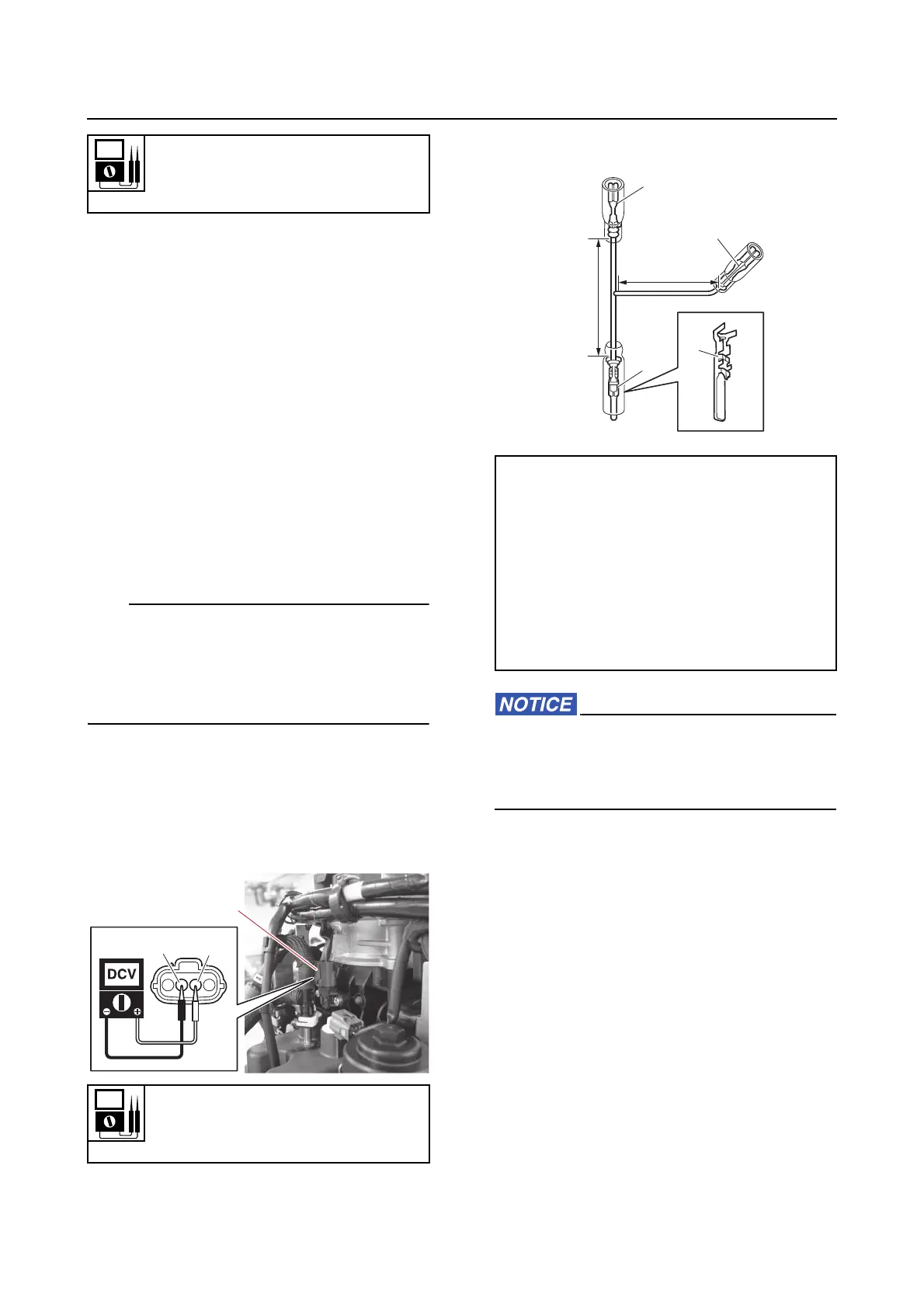
g. Make 3 test leads.
Make sure that the test leads do not con-
tact each other and cause a short circuit.
Otherwise, the fuse could blow when the
power is supplied.
h. Remove the intake air pressure/tem-
perature sensor.
See “ETV” (6-28).
i. Connect the special service tool “1”
and test leads “2” to the intake air pres-
sure/temperature sensor.
Input voltage
5 V
Orange (Or)–Black (B)
Input voltage
5 V
Orange (Or)–Black (B)
Test lead
Terminal, male “1”
8100-1466
Terminal, female “2”
8100-2567
Terminal, female “3”
(commercially available)
“a” = 100 mm (3.94 in)
“b” = 50 mm (1.97 in)