PTT unit
9-49
If the fluid is below the proper level, add the
recommended PTT fluid. Repeat steps (c)–(g)
until the fluid remains at the proper level.
i. Install a new O-ring and the reservoir
cap.
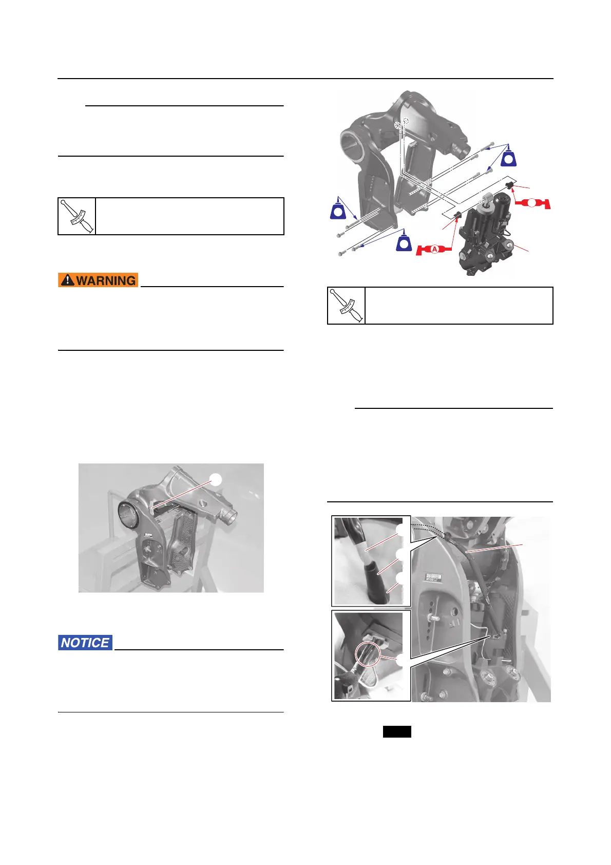
Installing the PTT unit
When removing or installing the PTT unit
with the power unit or upper case assembly
installed, make sure to suspend the out-
board motor.
1. Install:
• Bushing
(into the swivel bracket)
• PTT unit
a. Fully tilt the swivel bracket up, and then
support it using the tilt support lever
“1”.
b. Install the bushings “1” and PTT unit
“2”.
When removing or installing the PTT unit,
do not hold the PTT unit using the tilt cylin-
der. Otherwise, the pipe could break, caus-
ing PTT fluid to leak.
c. Route the PTT motor lead “a” through
the hole “b” in the swivel bracket, and
then install the grommet “c” on the PTT
motor lead to the hole “b”.
• Confirm that there is no torsion in the base
“d” of the PTT motor lead “a”.
• After the grommet “c” is installed, confirm
that the end of the white tape “e” on the PTT
motor lead is aligned with the end of the
grommet “c”.
2. Install:
•O-ring
• Adapter
• Upper mounting shaft
• PTT sensor
•Pin
Reservoir cap
7 N·m (0.7 kgf·m, 5.2 lb·ft)
PTT unit mounting bolt
55 N·m (5.5 kgf·m, 41 lb·ft)
1
1
2
AA
271271
LTLT
271271
LTLT
271271
LTLT