5-23
Engine control unit and component
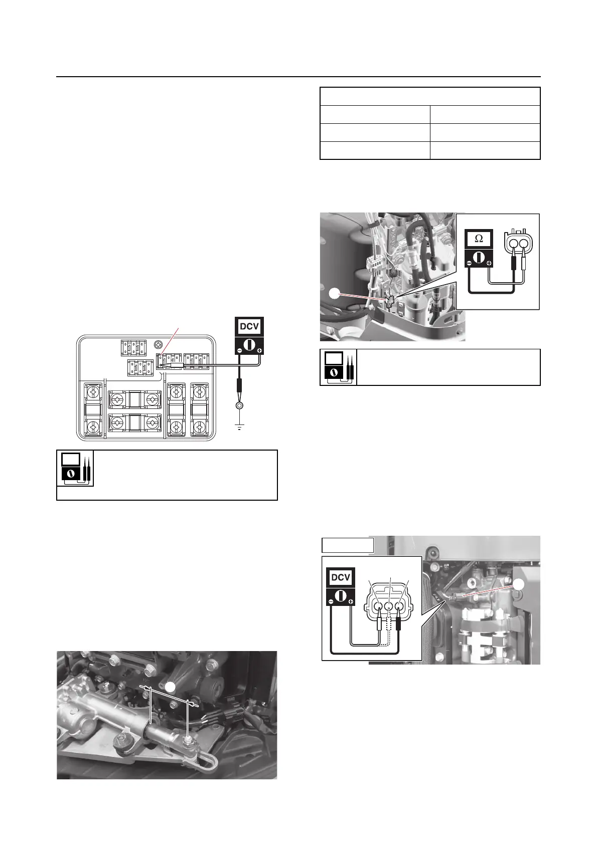
Checking the shift actuator relay
The shift actuator relay cannot be removed for
testing or replaced as a single unit because it
is a component part of the electrical manage-
ment box.
1. Check:
• Shift actuator relay
a. Connect the YDIS to display “Shift ac-
tuator relay”.
b. Turn the main switch or power switch
to ON, and then check that “ON” is dis-
played for “Shift actuator relay” on the
YDIS screen.
c. Remove the fuse cover.
d. Measure the input voltage between the
shift fuse “a” and ground.
e. Turn the main switch or power switch
to OFF.
f. Install the fuse cover.
Checking the shift actuator
1. Check:
•Shift actuator
a. Operate the Digital Electronic Control
to check the shift actuator rod stroke
“a” at the positions F, N, and R.
b. Disconnect the shift actuator coupler
“b”, and then measure the shift actua-
tor motor resistance.
c. Connect the shift actuator coupler.
Checking the cam position sensor
1. Check:
•Cam position sensor
a. Disconnect the cam position sensor
couplers “a”, “b”, and “c”.
b. Turn the main switch or power switch
to ON, and then measure the input volt-
age at the cam position sensor coupler.
Input voltage
12 V
Shift fuse “a”–Ground
Shift actuator rod stroke “a”
F 82.0 mm (3.23 in)
N 60.0 mm (2.36 in)
R 37.0 mm (1.46 in)
Motor resistance (reference data)
1.2 Ω