Engine control unit and component
5-24
c. Turn the main switch or power switch
to OFF.
d. Make 3 test leads.
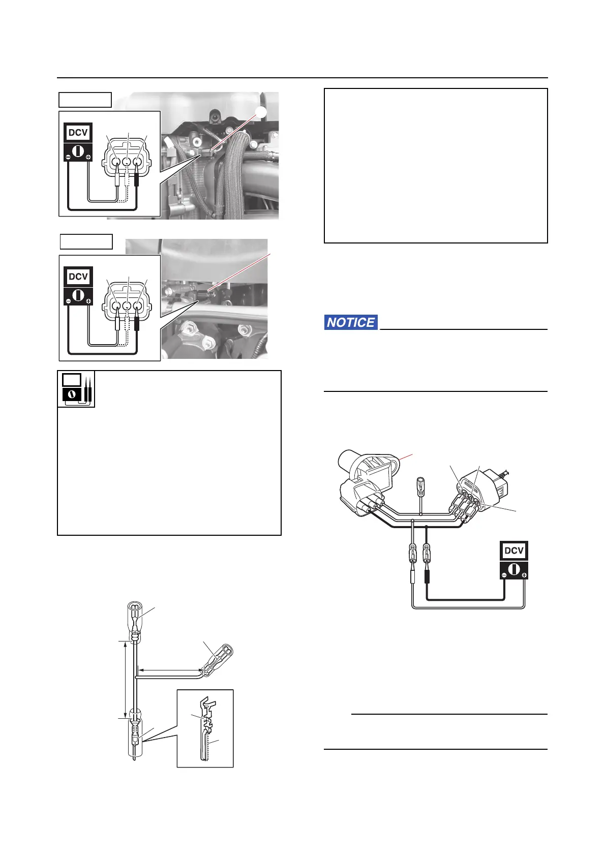
e. Remove the cam position sensors “1”.
f. Connect the test leads to the cam po-
sition sensor “1” and cam position sen-
sor coupler.
Make sure that the test leads do not con-
tact each other and cause a short circuit.
Otherwise, the fuse could blow when the
power is supplied.
g. Connect the tester probes to the test
leads.
h. Turn the main switch or power switch
to ON, and then measure the output
voltage when moving a screwdriver
close to the cam position sensor “1”.
Out of specification → Replace.
Using an analog circuit tester is recommend-
ed.
Input voltage
5 V
Orange (Or)–Black (B)
White/Green (W/G)–Black (B)
(PORT IN)
Orange (Or)–Black (B)
White/Black (W/B)–Black (B)
(STBD IN)
Orange (Or)–Black (B)
White/Blue (W/L)–Black (B)
(PORT EX)
Test lead
Terminal, male “1”
9E212-10303
Terminal, female “2”
9E212-11303
Terminal, female “3”
(commercially available)
“a” = 100 mm (3.94 in)
“b” = 50 mm (1.97 in)
“c” = Cutout area