5-53
PTT system
PTT system
Checking the PTT switch (on bottom
cowling)
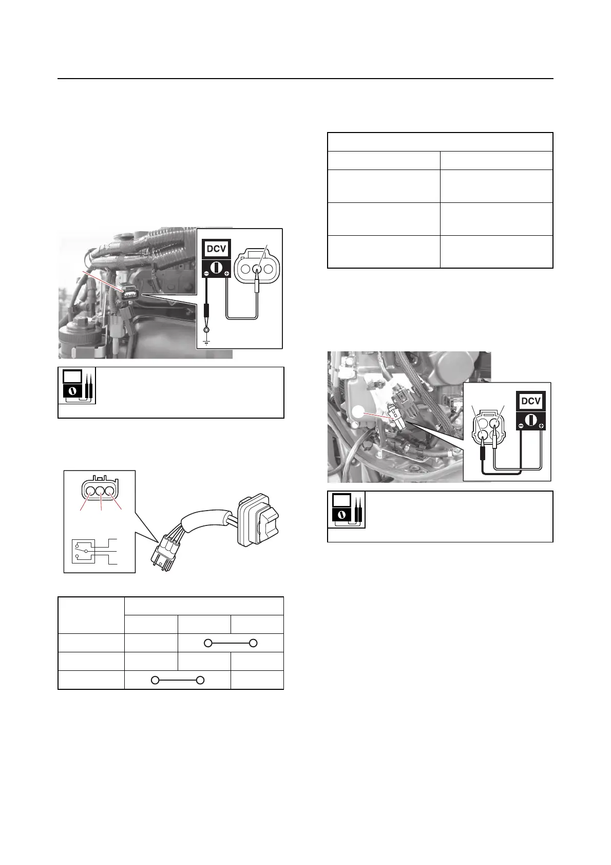
1. Check:
•PTT switch
a. Disconnect the PTT switch coupler “a”.
b. Measure the input voltage between the
PTT switch coupler terminal and
ground.
c. Check the PTT switch for continuity.
Replace if out of specification.
Checking the PTT sensor
1. Check:
•PTT sensor
a. Connect the YDIS to display “PTT sen-
sor”.
b. Tilt the outboard motor up and down,
and measure the PTT sensor output
voltage at the specified positions.
c. Disconnect the PTT sensor (sub lead)
coupler “a”.
d. Turn the main switch or power switch
to ON, and then measure the input volt-
age at the PTT sensor coupler.
e. Turn the main switch or power switch
to OFF, and then connect the PTT sen-
sor (sub lead) coupler.
Checking the PTT buzzer
1. Remove:
• Intake manifold (PORT)
See “Intake manifold” (6-24).
2. Check:
• PTT buzzer continuity
Out of specification → Replace the PTT
buzzer.
a. Remove the PTT buzzer.
PTT switch input voltage
12.0 V
Red (R)–Ground
Switch
position
Terminal
“a” “b” “c”
UP
Free
DN
Output voltage
Position Voltage
Tilt support lever up-
per position
4.07
Tilt support lever
lower position
3.57
Fully tilted-down po-
sition
0.93
PTT sensor input voltage
5 V
Orange (Or)–Black (B)