Shimming (counter rotation model)
8-62
5. Remove:
• Special service tools
6. Install:
• Determined propeller shaft shim
Measuring the forward gear backlash
and reverse gear backlash
• Spray anti-rust lubricant on the gears and
bearings before installation. Do not apply
gear oil to the parts. Otherwise, correct mea-
surements cannot be obtained.
• Keep the parts free of foreign material, such
as dirt and lint.
• When measuring the forward gear or reverse
gear backlash, use the shims of the speci-
fied thickness for the reverse gear shim (T1)
and forward gear shims (T2), and use the
shims of the selected thickness for the pin-
ion shims (T3).
1. Install:
• Adapter assembly
• Specified reverse gear shim (T1)
• Thrust bearing
• Reverse gear assembly
See “Installing the forward gear” (8-34).
• Determined pinion shim (T3)
• Spacer
• Drive shaft assembly
•Pinion
• Pinion nut
• Spacer
• Drive shaft ring nut
See steps 1 and 2 in “Installing the drive
shaft” (8-34).
• Do not reuse shims.
• Check that the drive shaft turns smoothly.
2. Install:
• Specified forward gear shim (T2)
• Propeller shaft/propeller shaft housing as-
sembly
•Key
• Claw washer (do not bend the tabs)
• Ring nut
See steps 2–5 in “Installing the propeller
shaft housing assembly” (8-25).
• Do not reuse shims.
• Check that the drive shaft turns smoothly.
3. Install:
•Shift rod
• Shift rod guide plate (temporarily)
See step 1 in “Installing the water pump
and shift rod (counter rotation model)”
(8-16).
4. Measure:
• Forward gear backlash
Out of specification → Repeat steps from
the selection of the reverse gear shim (T1)
and forward gear shims (T2).
When measuring the forward gear backlash
on the counter rotation model, the torpedo of
the lower unit should point upward.
a. Install the shift rod and shift rod guide
plate temporarily, set the gear shift to
the N position.
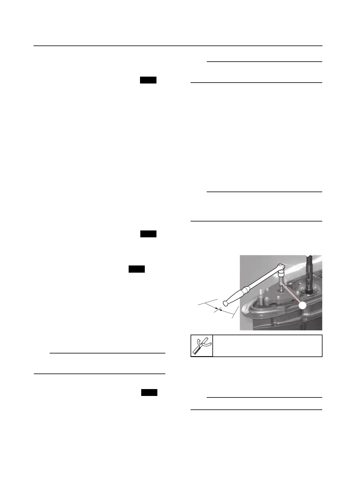
b. Set up the special service tools, and
then tighten the center bolt “1” or “a” to
the specified torque.
Without the attachment “b”.
Shift rod socket “1”
90890-06950