Outboard motor troubleshooting
4-8
Trouble code and checking step
For code number 300 and higher checking steps, see the Helm master EX rigging guide (6X9-28197-
**).
The descriptions enclosed by < > are applicable to multiple engine installations.
*1: Crankshaft position sensor
*2: See the Helm Master EX rigging guide.
—: Not applicable
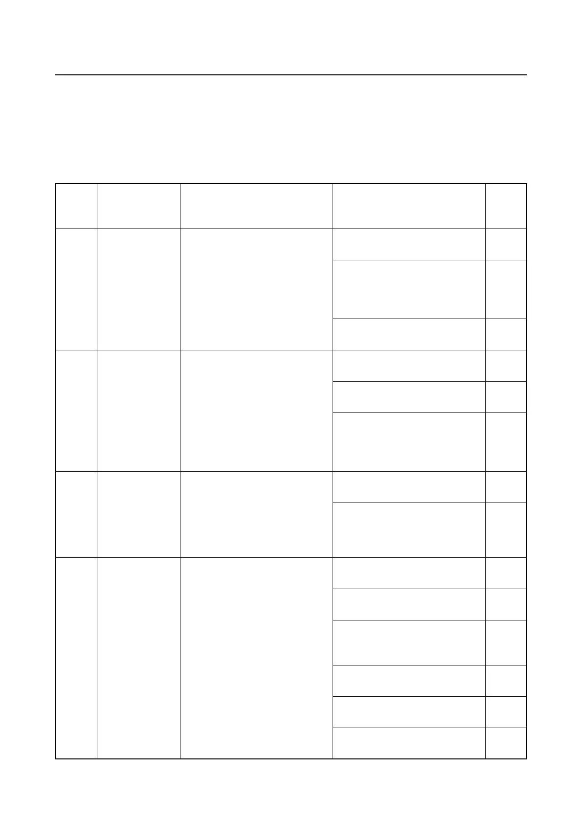
Trou-
ble
code
Item (Condi-
tion)
Symptom Checking steps
See
page
13
Pulser coil *1
(Irregular sig-
nal)
“Check Engine” is displayed.
Engine does not restart.
<Engine speeds do not syn-
chronize>
Measure the crankshaft posi-
tion sensor input voltage.
5-35
Check for wiring continuity
between the crankshaft posi-
tion sensor and the engine
ECM.
A-14
Check the protrusions on the
pickup rotor for damage.
7-77
15
Engine tem-
perature sensor
(Out of specifi-
cation)
“Check Engine” is displayed.
Degraded acceleration perfor-
mance.
Declining maximum engine
speed.
<Engine speeds do not syn-
chronize>
Measure the engine tempera-
ture sensor input voltage.
5-37
Measure the engine tempera-
ture sensor resistance.
5-37
Check for wiring continuity
between the engine tempera-
ture sensor and the engine
ECM.
A-14
17
Knock Sensor
1 (Irregular sig-
nal)
“Check Engine” is displayed.
High engine idle speed.
Reduce engine speed ap-
proximately 300 r/min.
<Engine speeds do not syn-
chronize>
Measure the knock sensor re-
sistance.
5-39
Check for wiring continuity
between the knock sensor
and the engine ECM.
A-14
19
Battery voltage
(Below speci-
fied voltage)
Battery voltage and battery
alert are displayed.
High engine idle speed.
Engine does not restart (de-
pends on battery condition).
Check the battery capacity
and specific gravity.
10-9
Check the fuse.
5-10
A-16
Check the battery cable and
terminals for proper connec-
tion.
10-9
Measure the lighting coil re-
sistance.
5-34
Measure the rectifier/regulator
output voltage.
5-34
Check
the rectifier/regulator
for continuity.
5-34