8-3
Propeller and water inlet cover
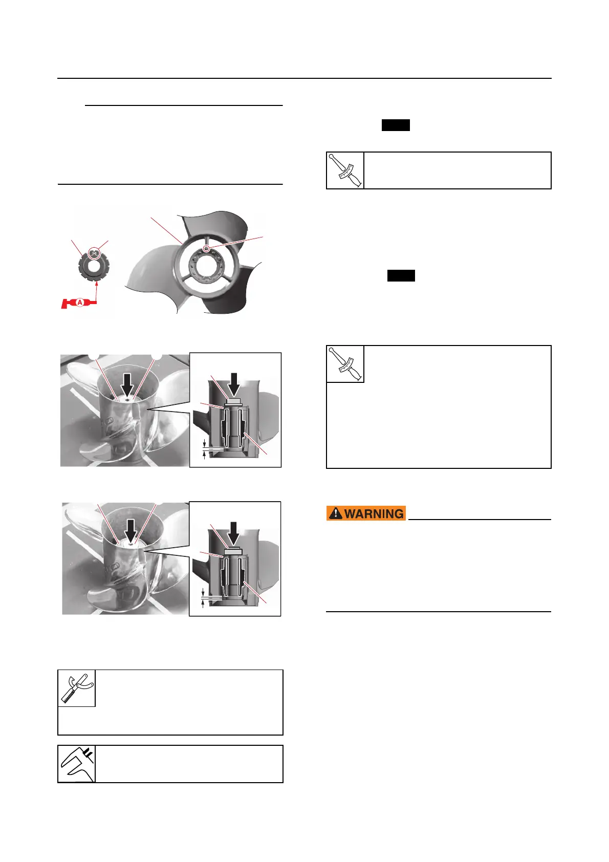
• Align the mark “a” on the damper “1” with
the mark “b” on the propeller “2”.
• Install the damper “1” using the special ser-
vice tools and spacer “3” to the specified in-
stallation depth “c”.
A
B
Installing the water inlet
1. Install:
•O-ring
• Drain screw
2. Fill:
•Gear oil
See step 5 in “Changing the gear oil by re-
moving the drain screw” (10-17).
3. Install:
•O-rings
• Oil level plug
• Oil filler plug
• Lower water inlet covers
• Upper water inlet covers
Installing the propeller
• Make sure to disconnect the battery ca-
bles from the battery, and remove the clip
from the engine shut-off switch.
• When loosening or tightening the propel-
ler nut, do not hold the propeller using
your hands.
1. Install:
• Spacer “1”
•Propeller “2”
• Spacer “3”
•Washer “4”
• Propeller nut “5”
A. Worldwide
B. USA and Canada
Needle bearing attachment “4”
90890-06608
Driveshaft bearing installer “5”
YB-06110
Installation depth “c”
13.5–16.3 mm (0.53–0.64 in)
a
b
1
2
4
1
3
3 4
c
5
1
3
3 5
c
Drain screw
2.5 N·m (0.25 kgf·m, 1.8 lb·ft)
Oil level plug
2.5 N·m (0.25 kgf·m, 1.8 lb·ft)
Oil filler plug
2.5 N·m (0.25 kgf·m, 1.8 lb·ft)
Lower water inlet cover bolt
2.5 N·m (0.25 kgf·m, 1.8 lb·ft)
Upper water inlet cover bolt
2.5 N·m (0.25 kgf·m, 1.8 lb·ft)