Steering actuator and steering arm
9-39
*. Apply Valvoline X-ALL.
h. Tighten the steering arm joint bolts “1”.
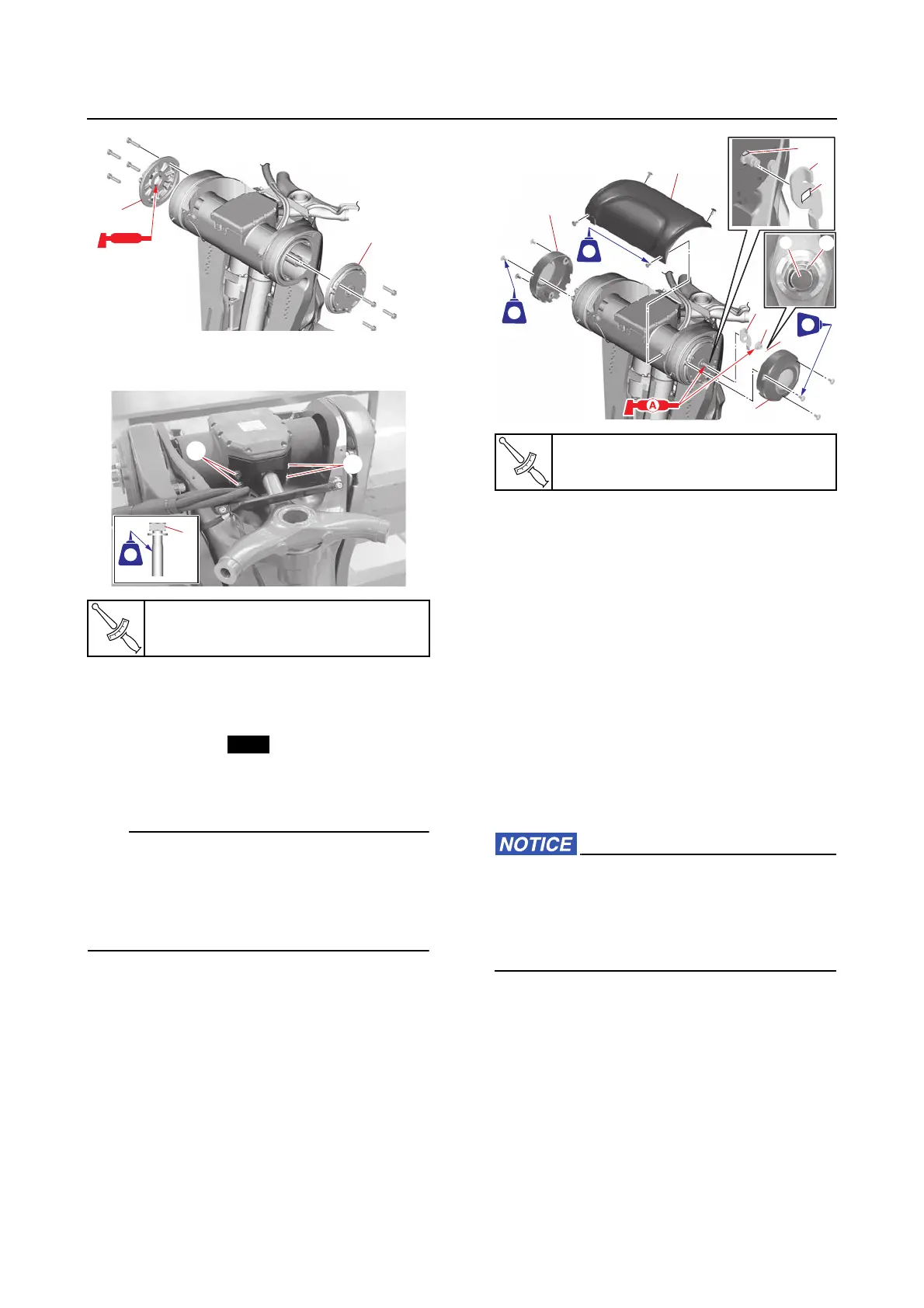
3. Install:
• Manual steering lever “1”
• Steering shaft end nut “2”
• Cotter pin “3”
• Swivel bracket top cover “4”
• Clamp bracket side covers “5”
• Align the hole “a” in the manual steering le-
ver “1” with the flat sides “b” of the steering
shaft.
• Bend the ends of the cotter pin “3” along the
shaft “c” as shown.
Installing the steering actuator (with
the power unit installed)
If the steering actuator is removed, the calibra-
tion is required after installation. See “Calibra-
tion (6X9 Digital Electronic Control)” (3-66).
1. Install:
• SCU lead
• Steering actuator
See “Installing the steering actuator (with
the power unit removed)” (9-37).
2. Connect:
• SCU positive terminal “a”
• SCU couplers “b”, “c”
• SCU ground terminal “d”
When tightening the electrical manage-
ment box terminal nuts, do not exceed the
specified torque. Otherwise, the base of the
electrical management box could be dam-
aged.
Steering arm joint bolt “1”
27 N·m (2.7 kgf·m, 20 lb·ft)
Steering shaft end nut “2”
60 N·m (6.0 kgf·m, 44 lb·ft)
4
5
5
3
2
1
c
3
b
1
a
242242
LTLT
572572
LTLT
242242
LTLT