7-68
Cylinder head
•Anode
•Gasket
• Anode cover grommet
4. Install:
• Anode assembly
Do not apply grease, oil, or paint to the an-
odes.
Installing the cylinder head
Before assembling the cylinder head, check
the cylinder head bolts. See “Checking the
cylinder head bolt” (7-60).
1. Install:
•Grommet
Align the protrusion “a” on the grommet with
the rib “b” on the cylinder block. Make sure
that no portion of the grommet, except the
protrusion, protrudes above the mating sur-
face of the cylinder block.
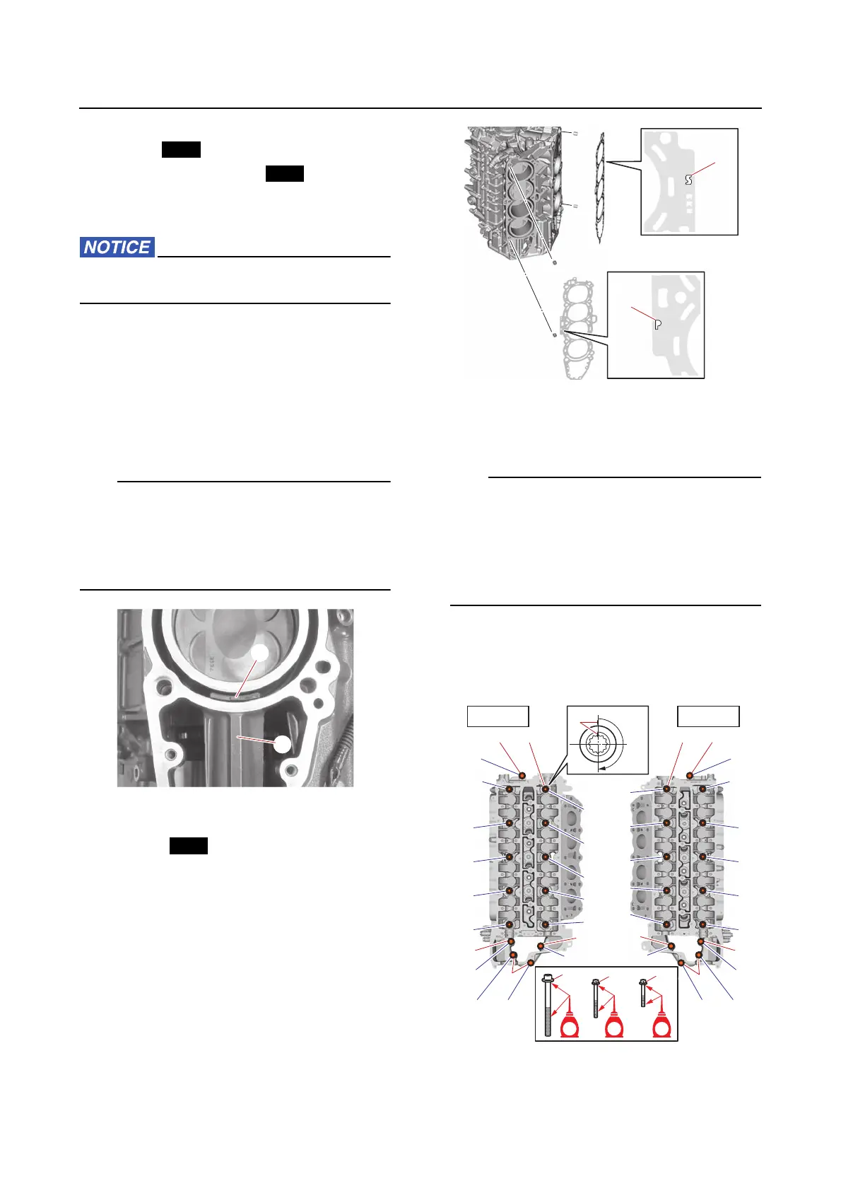
2. Install:
•Dowel
•Gaskets
• Cylinder head (PORT)
• Cylinder head (STBD)
• Cylinder head bolts (M11)
• Cylinder head bolts (M8)
a. Install a new gasket with the “P” mark
“a” on port side, and a new gasket with
the “S” mark “b” on starboard side.
b. Tighten the cylinder head bolts (M11)
“1” to the specified torques in 2 stages
and in the order [1], [2], and so on.
• Tighten the M11 bolts using a triple square
socket.
• In the 2nd stage, mark the M11 bolts and
cylinder head with paint marks “a”, and then
tighten the M11 bolts 180° from the marks
on the cylinder head.
c. Tighten the cylinder head bolts (M8) “2”
and “3” to the specified torques in 2
stages and in the order [11], [12], and
so on.
180°
a
EEEE EE
1
2
2
2
2
2
3
[9][9]
[5][5]
[1][1]
[4][4]
[8][8]
[14][14]
[15][15]
[10][10]
[6][6]
[2][2]
[3][3]
[7][7]
[11][11]
[12][12] [13][13]
1 3
[9][9]
[5][5]
[1][1]
[4][4]
[8][8]
[14][14]
[15][15]
[10][10]
[6][6]
[2][2]
[3][3]
[7][7]
[11][11]
[12][12][13][13]
PORT
STBD
1 2 3
2