Power unit assembly
7-15
Removing the power unit
1. Remove:
• Bottom cowling cover and apron cover
See “Bottom cowling cover and apron
cover” (9-1).
• Bottom cowlings
See “Bottom cowling (PORT and STBD)”
(9-3).
• Aprons
See “Apron” (9-8).
•Dipstick
See “Intake manifold” (6-24).
• Gear oil changing system hoses
See “Cooling water hose and gear oil
changing hose” (9-9).
• Fuel rail covers
See “Fuel hose assembly” (6-12).
• Low-pressure fuel pump holder
(from the low-pressure fuel pump bracket)
See “Low-pressure fuel pump” (6-6).
After removing the low-pressure fuel pump
holder, support the low-pressure fuel pump,
such as by securing it to the power unit as-
sembly using a string, and so on.
2. Remove:
• Exhaust joint assembly
See “Exhaust joint (outside)” (7-7).
3. Remove:
• PTT motor lead “1”
• SCU positive lead “2”
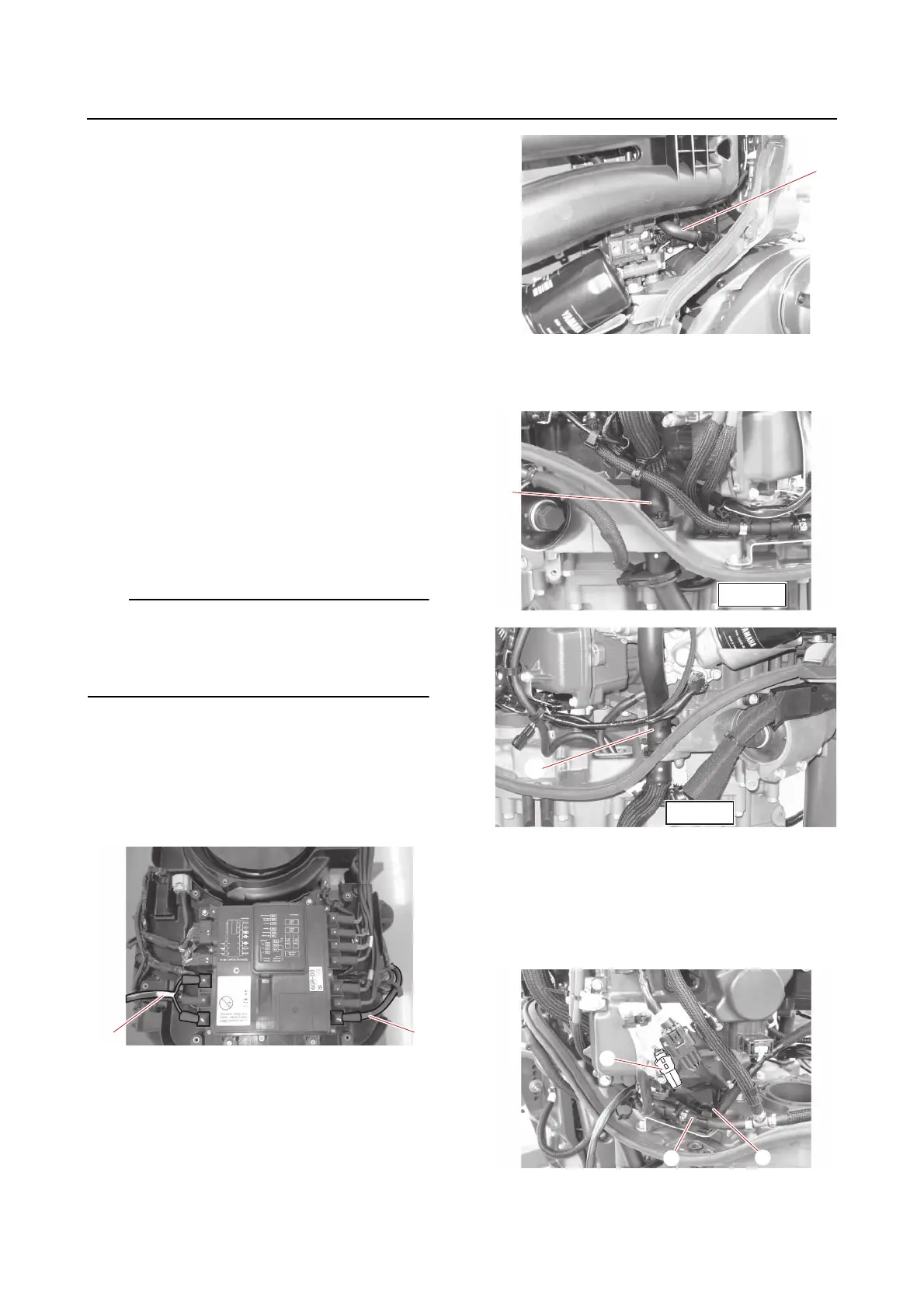
4. Disconnect:
• Flushing hose “1”
(from the joint)
5. Disconnect:
• Cooling water hoses “1”, “2”
(from the joint)
6. Disconnect:
• PTT sensor coupler “1”
• Fuel hose “2”
(from the holder bracket)
• Wire harness “3”
(from the holder bracket)
7. Disconnect:
• SPS lead coupler “1”