5-21
Engine control unit and component
Continuity between the engine ECM
coupler “c” and the electrical manage-
ment box coupler “d”:
e. Measure the input voltage at the engine
ECM.
See “Checking the engine ECM circuit”
(5-19).
f. No problems were found in the preced-
ing step → Replace the electrical man-
agement box.
Checking the ETV and TPS
TPS 1 and TPS 2 are components of the ETV,
which cannot be disassembled.
Do not loosen the throttle stop screw nut or
turn the throttle stop screw.
1. Check:
• TPS 1 and TPS 2
a. Connect the YDIS to display “TPS 1”
and “TPS 2”.
b. Start the engine, warm it up for 5–10
minutes, and then stop it.
c. Turn the main switch or power switch
to ON, and then measure the TPS out-
put voltages when the Digital Electric
Control lever is at the fully closed posi-
tion.
d. Turn the main switch or power switch
to OFF.
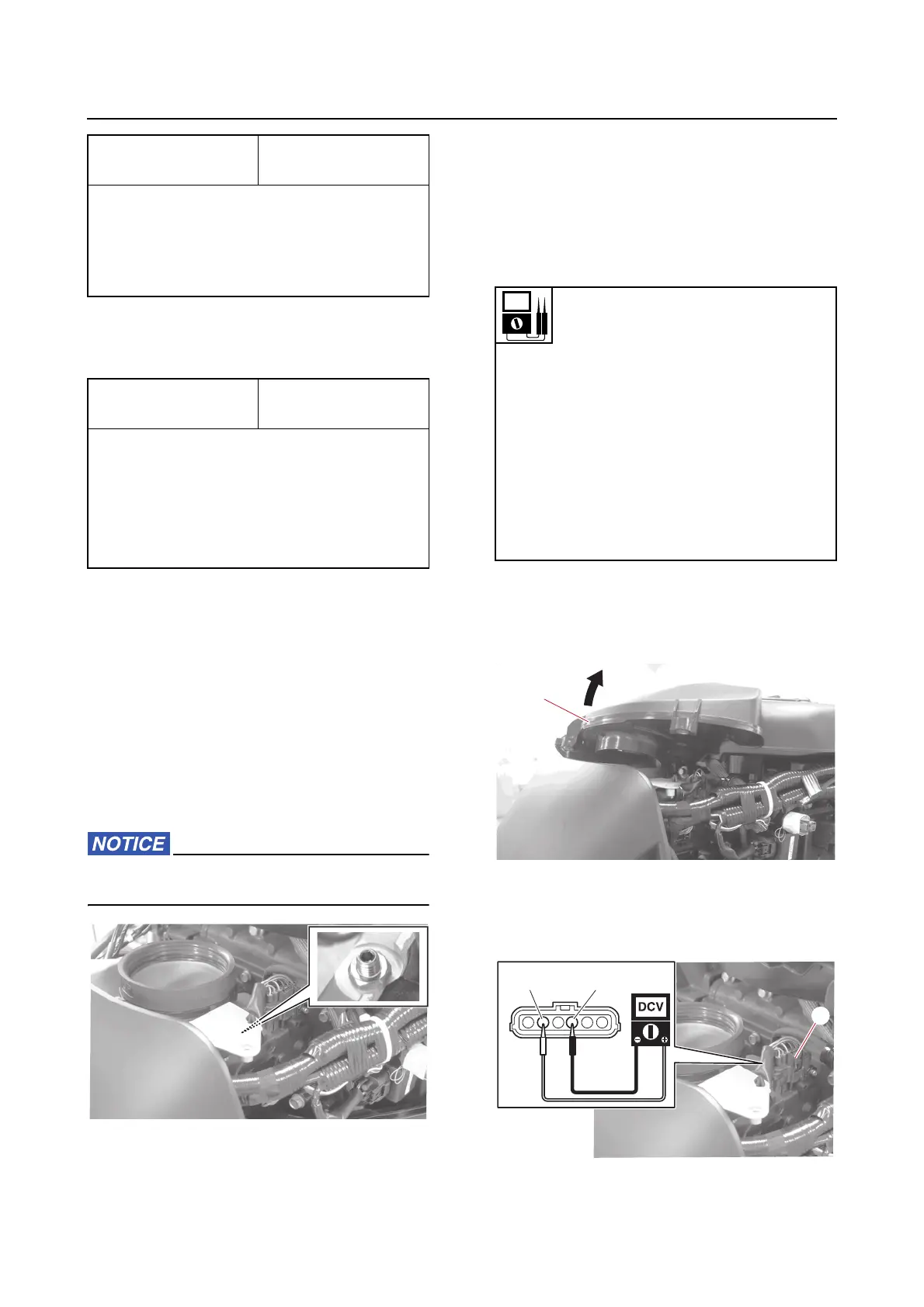
e. Disconnect the intake silencer “1” from
the ETV.
f. Disconnect the ETV coupler “a”.
g. Turn the main switch or power switch
to ON, and then measure the TPS input
voltage at the ETV coupler.
Terminal of coupler
“b”
Terminal of coupler
“d”
25 – 22
34 – 2
34 – 20
33 – 16
Terminal of coupler
“c”
Terminal of coupler
“d”
1–18
2–9
17 – 7
11 – 23
26 – 15
TPS 1 output voltage at throttle
valve fully closed (reference data)
0.850 V
TPS 2 output voltage at throttle
valve fully closed (reference data)
2.840 V
TPS 1 output voltage at throttle
valve fully open (reference data)
4.340 V
TPS 2 output voltage at throttle
valve fully open (reference data)
4.640 V